Option 100 Fault Location and SRL 1-11
Introduction and Measurement Theory
Cable Impedance and Structural Return Loss Measurement Theory
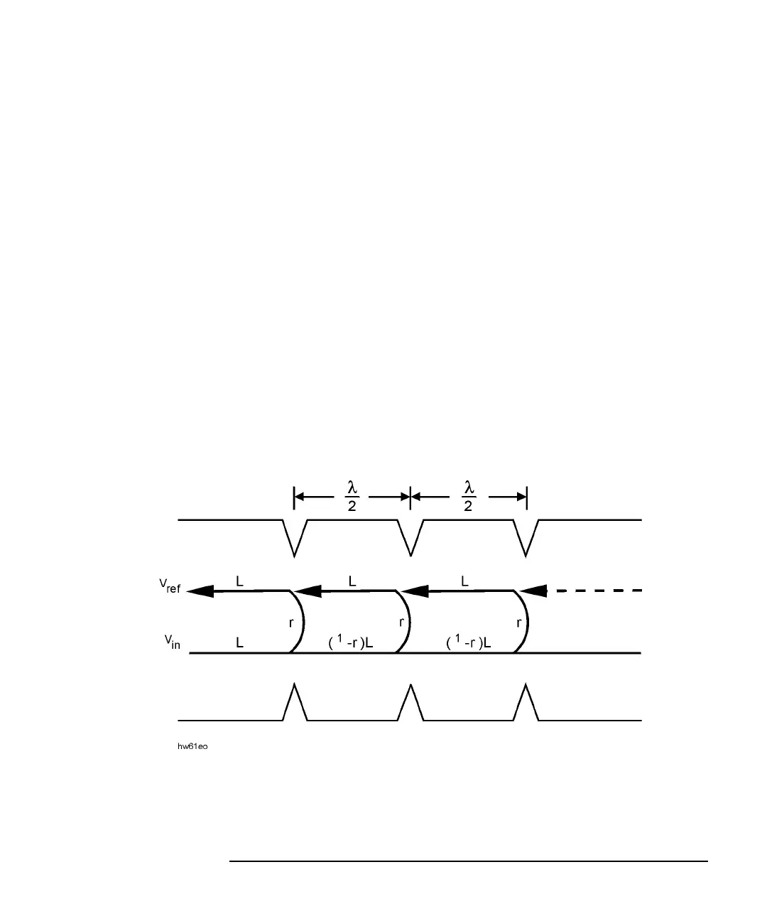
Figure 1-2 diagrams reflections from bumps in a cable. We can combine
the energy reflected by each bump in a cable and make a few basic
assumptions, to mathematically describe SRL by the series shown in
Equation 9.
Equation 9
V
ref
= reflected Voltage
V
in
= incident Voltage
L = cable loss
Γ = reflection coefficient of the bumps
The bumps are assumed to be uniform in reflection and spaced by a
wavelength/2 separation.
Figure 1-2 Periodic Bumps in a Cable
V
ref
V
in
LΓL[]V
in
L 1 Γ–()LΓLL[]V
in
L 1 Γ–()L 1 Γ–()LΓLLL[]…++ +=