3-8 Option 100 Fault Location and SRL
Making Fault Location Measurements
How to Make and Interpret Fault Location Measurements
Using Calibration Standards to Calibrate the
Instrument
To calibrate the instrument using calibration standards, perform the
following steps:
1. Press . (Fault location must already be
selected as the type of measurement.)
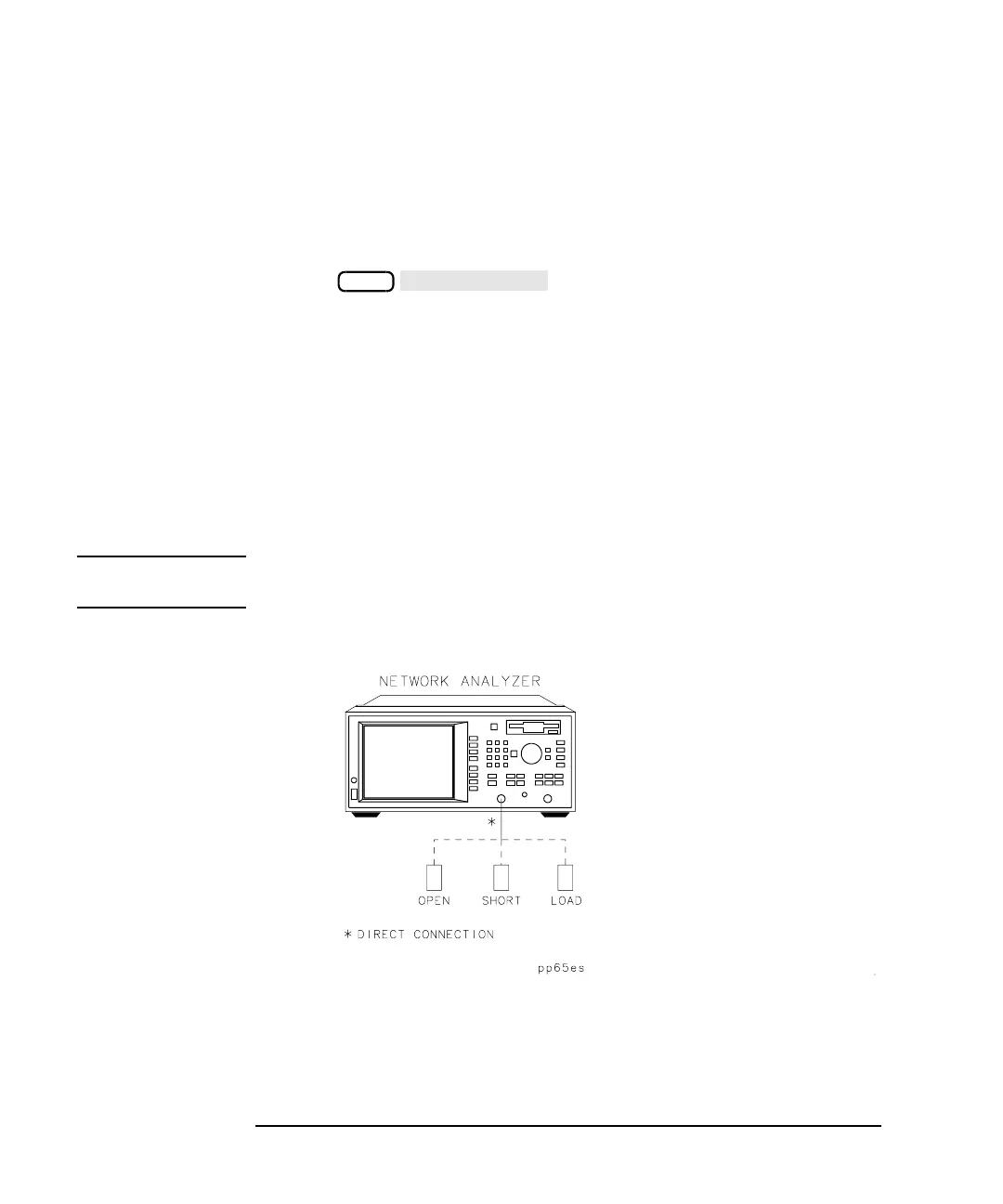
2. Follow the prompts on the analyzer's screen to connect the open,
short, and load to the analyzer's RF OUT (or PORT 1) test port. (See
Figure 3-1.) Or, if your measurement reference plane is the end of a
test lead cable, connect the standards to the end of the test lead cable.
3. After the calibration is complete, a “C” is displayed in the channel
annotation area in the upper right-hand corner of the analyzer's
display. The “C” indicator is a visual verification that a full band (not
instrument default) calibration is in use and has been completed
properly.
NOTE A full band calibration is valid over the entire frequency range of the
analyzer and is valid for any frequency setting.
Figure 3-1 Calibrate the Instrument
CAL
 Loading...


