Maintaining the Instrument
Aligning the Vial Loader (G1289/G1290 only)
98
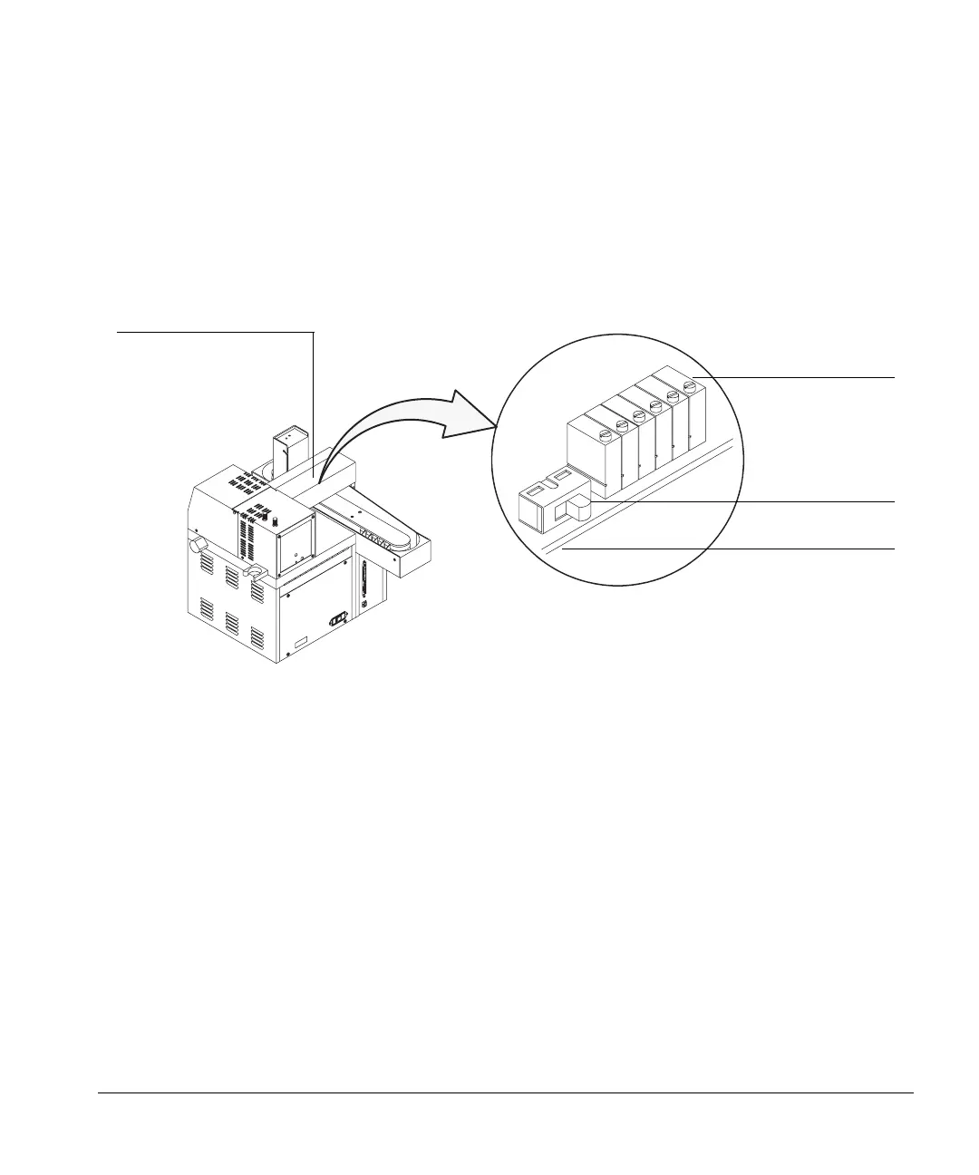
The potentiometers are located on a small printed circuit board and are
labelled P1 through P6. See Figure 23. Use the procedure on page 99 to identify
which potentiometer you need to adjust. P1 and P2 adjust the height of the
fork; these are the y-axis adjustments. P3 through P6 adjust the horizontal
position of the fork at four different locations; these are x-axis adjustments.
Figure 23. Potentiometers controlling the vial gripper arm
To determine if you need to turn a potentiometer clockwise or
counterclockwise, refer to Table 9. Then use a small flathead screwdriver to
turn the adjusting screw.
Horizontal loader assembly
Potentiometers
Horizontal loader
Vial size
The potentiometers are located on the
PC board
selection switch
PC board for the horizontal loader
6
5
4
3
2
1

 Loading...