Agilent 1260 Infinity II Preparative Autosampler User Manual 19
Introduction
1
Operating Principle
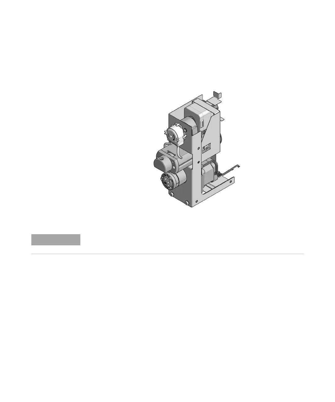
Hydraulic Box
The hydraulic box comprises two main assemblies: metering device, and
injection valve.
Figure 7 Hydraulic Unit
Analytical Head
The analytical head is driven by the stepper motor that is connected to the
drive shaft by a toothed belt. The drive nut on the spindle converts the circular
movement of the spindle to linear motion. The drive nut pushes the sapphire
piston against the tension of the spring into the analytical head. The base of
the piston sits on the large bearing of the drive nut, which ensures the piston
is always centered. A ceramic ring guides the movement of the piston in the
analytical head. The home position of the piston is sensed by an optical sensor
on the hydraulic unit board while the sample volume is determined by
counting the number of steps from the home position. The backward
movement of the piston (driven by the spring) draws sample from the vial.
The replacement hydraulic box excludes the injection valve and metering head assemblies.
 Loading...