Agilent N5161A/62A/81A/82A/83A MXG Signal Generators Service Guide
Assembly Replacement
A3 RF Assembly (N5162A, with and without Option 012, N5182A with Option 012, and N5182A Option 1EM,
with and without Option 012)
3-35
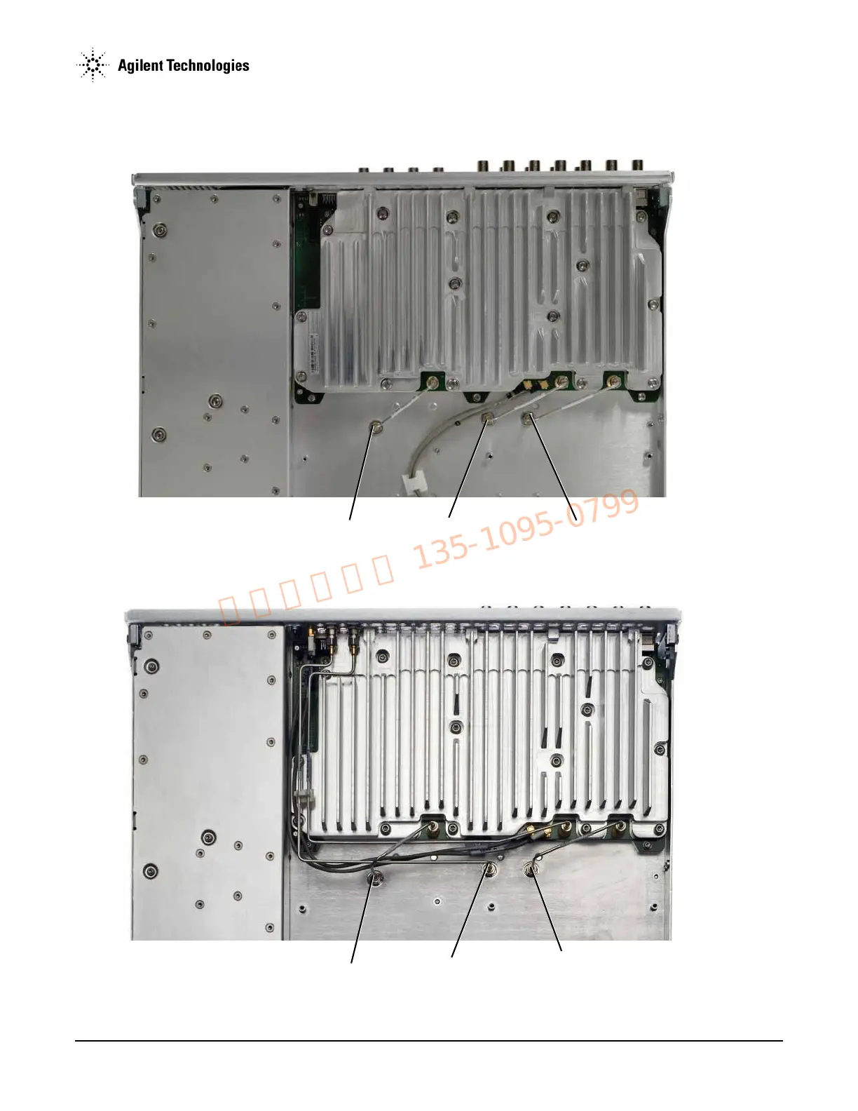
Figure 3-17 A3 RF Assembly - N5162A and N5182A Option 1EM
W5
W17
W7
W5
W6
W7
Instruments without Option 012
Instruments without Option 012