Agilent Technologies N5161A/62A/81A/82A/83A MXG Signal Generators Service Guide
Post-Repair Procedures and Performance Verification
Leveled Output Power Verification (N5161A/62A
1
/81A/82A Only)
4-13
Leveled Output Power Verification (N5161A
1
/62A
1
/81A/82A Only)
This test verifies that the output power from the signal generator is within defined limits. The following table lists the preferred equipment
for this test.
• “N5161A
1
/81A Output Power Test Procedure” on page 4-13
• “N5162A/82A Output Power Test Procedure” on page 4-15
N5161A
1
/81A Output Power Test Procedure
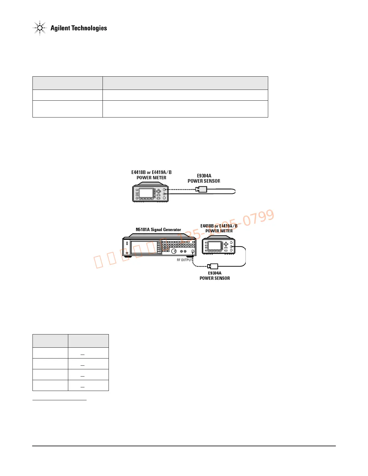
1. Zero and calibrate the power sensor to the power meter:
2. Connect the equipment as shown:
3. Preset the signal generator: Press
Preset.
4. Turn RF on: Press
RF On/Off so that the RF On/Off LED lights.
5. Turn modulation off: Press
Mod On/Off so that the Mod On/Off LED turns off.
6. Set the frequency: Press
Frequency and enter the first frequency value listed in Table 4-10.
1
The N5161A/62A performs the identical internal tests as in the MXG via a LAN connection to a Web Server. The front panel displays all hardkeys, softkeys and test results
as depicted in the illustration. For information on Web-Enabled Control refer to
“Accessing the MXG Web-Enabled Page” on page 1-18 and to the Programming
Guide.
Test Equipment Recommended Model
Power Meter Agilent E4418B or E4419A/B E-Series power meter
Power Sensor,
Input: Type-N (m)
Agilent E9304A
Table 4-10Leveled Output Power Limits
Frequency Limits (dB)
125 MHz <
0.6dB
275 MHz <
0.6dB
338 MHz <
0.6dB
425 MHz <
0.6dB