Agilent N5161A/62A/81A/82A/83A MXG Signal Generators Service Guide
Troubleshooting
Pulse Modulation Problems (N5183A)
1-51
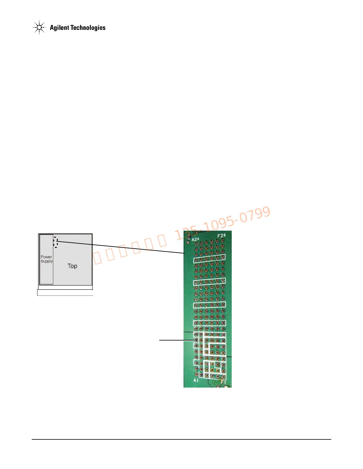
• If the measured voltage is not > 2.5 Vp–p on ALC J1-E3, replace the A3 RF assembly.
• If the measured voltage is > 2.5 Vp–p on ALC J1-E3, replace the A7 Micro Deck.
4. Go to Chapter 4, "Post-Repair Procedures and Performance Verification".
Pulse Modulation Problems (N5183A)
1. Remove the external cover and the top inside cover. Refer to Chapter 3, "Assembly Replacement" for instructions on removing the
instrument covers.
2. Set up the signal generator:
a. Press
Preset.
b. Press
FREQ > 5 > GHz.
c. Press
RF On/Off to On.
d. Press
AMPTD > 0 > dBm.
e. Press
Pulse > Pulse Off On to On.
f. Press
Pulse Period > 4 > usec.
g. Press
Pulse Width > 2 > usec.
3. Using a spectrum analyzer, verify that pulse modulation is present on the RF output.
4. Press FREQ > 2 > GHz.
5. Using a spectrum analyzer, verify that pulse modulation is present on the RF output.
6. If no pulse modulation is present at either frequency, replace the A3 RF Assembly and go to step 11.
7. If pulse modulation is present at 5 GHz, but is not present at 2 GHz, replace the A3 RF Assembly and go to step 11.
Figure 1-21 ALC J1-A7