Agilent N5161A/62A/81A/82A/83A MXG Signal Generators Service Guide
Troubleshooting
Troubleshooting Assembly Level Problems
1-36
9. Refer to Figure 1-11. Using the voltmeter, measure A3J10-B16.
• If A3J10-B16 is ∼12V, perform the following steps:
a. Replace the A3 RF assembly.
b. Go to Chapter 4, "Post-Repair Procedures and Performance Verification".
• If A3J10-B16 is not ∼12V, replace the A1 Power Supply.
A7 Micro Deck (N5183A)
• LEDs on page 1-36
• Power Supplies on page 1-37
LEDs
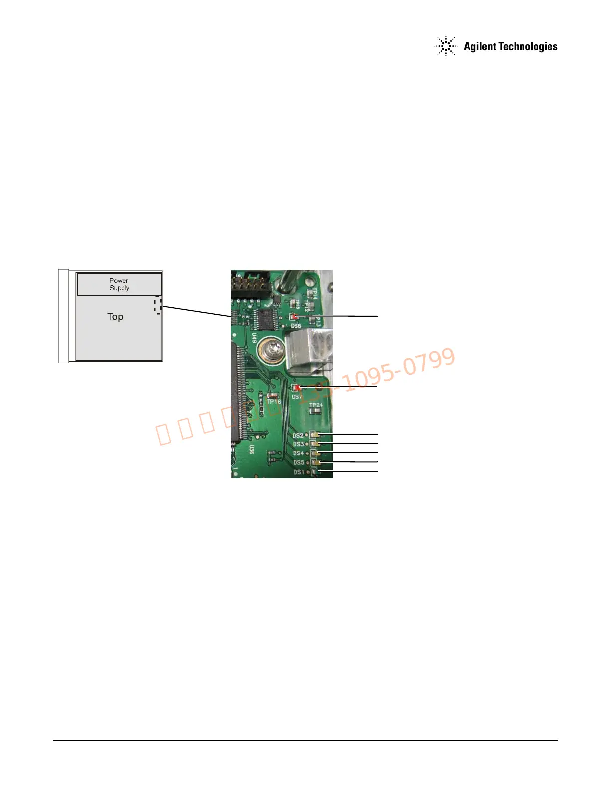
This procedure uses the LEDs on the A7 Micro Deck (Figure 1-12) for troubleshooting.
Figure 1-12Micro Deck LEDs
1. Remove the external cover and the top inside cover. Refer to Chapter 3, "Assembly Replacement" for instructions on removing the
instrument covers.
2. Turn the signal generator on.
3. Observe the LEDs shown in Figure 1-12.
• DS1 (green) LED normal operation: blinks twice, then pauses and repeats.
a. If normal operation is not present, check LED DS7.
b. If DS7 is on, check DS7 as described below.
• DS2 to DS5 (amber) LEDs have no significance in troubleshooting the instrument.
• DS6 (red) LED is normally off. If DS6 is on, it indicates FPGA code is missing.
— Reload the firmware.
• DS7 (red) LED is normally off. When DS7 is on, it indicates a missing PCI clock.
a. Check J1-F24 (see Figure 1-13 on page 37 for test point locations) for a sine wave (>3 Vp–p at ∼32 MHz, period ∼31 ns).
b. If the signal is < 3 Vp–p:
1. Replace the A3 RF assembly.
2. Go to Chapter 4, "Post-Repair Procedures and Performance Verification".