Agilent N5161A/62A/81A/82A/83A MXG Signal Generators Service Guide
Troubleshooting
Troubleshooting Assembly Level Problems
1-37
c. If the signal is > 3 Vp–p:
1. Replace the A7 Micro Deck.
2. Go to Chapter 4, "Post-Repair Procedures and Performance Verification".
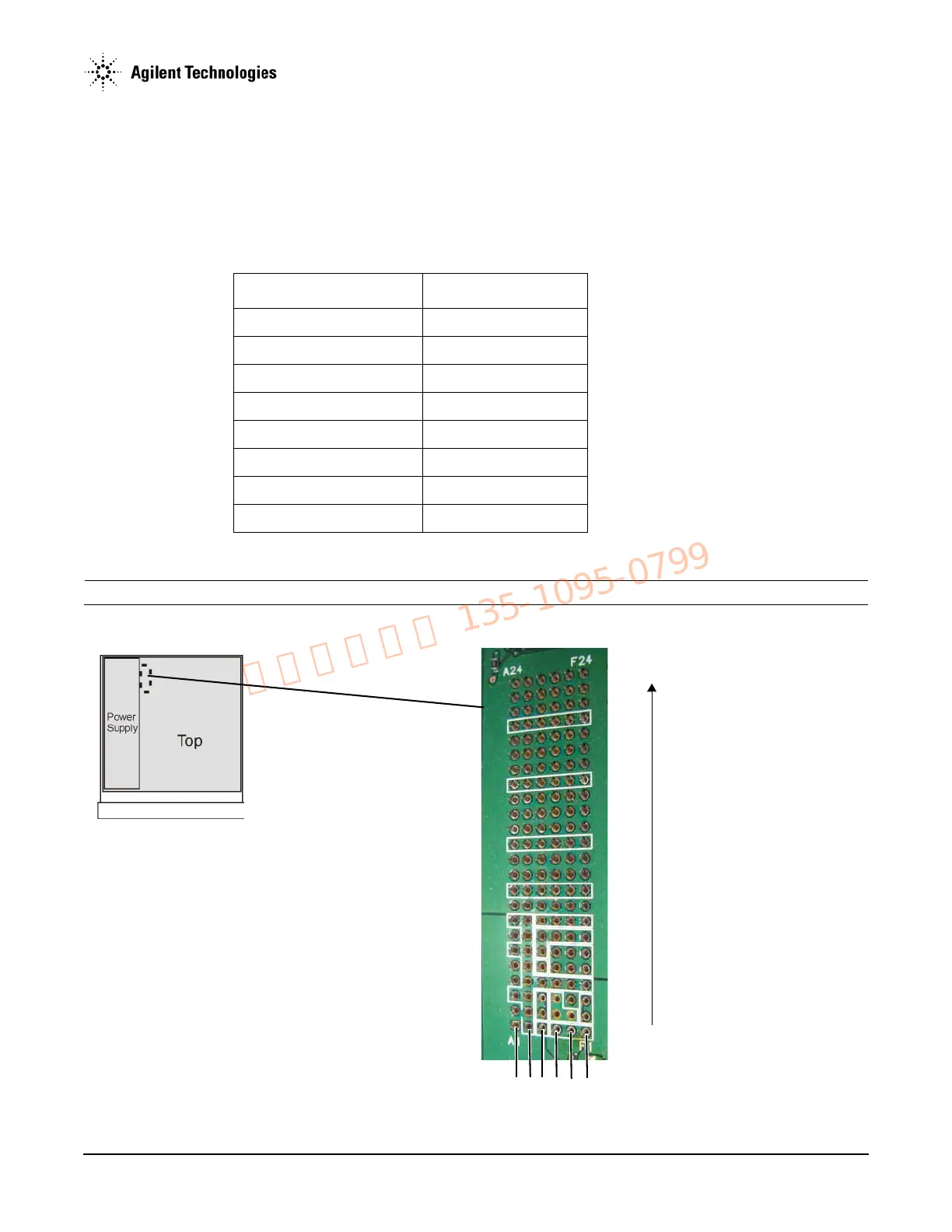
Power Supplies
The A3 RF assembly provides the voltages shown in Table 1-5 to the corresponding pins on the ALC J1 connector on the A7 Micro Deck.
1. Measure the voltages on the A7 Micro Deck ALC J1 connector pins shown in Table 1-5.
NOTE There is no “J1” label on this side of the circuit board.
Figure 1-13 ALC J1 connector pins
Table 1-5 A7 Micro Deck Voltages
Voltage ALC Connector/Pin
–15V ± 5% (analog bus) J1-C1
–7V ± 5% (analog bus) J1-C1/D1/E1/F1
+15V ± 5% (analog bus) J1-C2/C3
+5V ± 5% (analog bus) J1-D2/E2/D3
+9.5V ± 5% (analog bus) J1-F2/F3
+5V ± 5% (digital bus) J1-C5
+3.3V ± 5% (digital bus) J1-D5/E5/F5/D6/E6/F6
+12V ± 5% (digital bus) J1-C6/C7/D7/E7/F7