Agilent N5161A/62A/81A/82A/83A MXG Signal Generators Service Guide
Troubleshooting
Troubleshooting Assembly Level Problems
1-35
7. Refer to Figure 1-10. Use a voltmeter with a small probe to measure A6J5-1; it should be ∼12V.
• If A6J5-1 is ∼12V:
— Measure the connections in Table 1-4.
— If the voltages are not present, replace the A6 DC-AC Inverter Interface Board.
— If the voltages are present, replace the LCD Display assembly.
• If A6J5-1 is not ∼12V, measure A6J1-3 or A6J1-4.
— If J1-3 or J1-4 is ∼12V, replace the A6 DC-AC Inverter Interface and LCD assemblies.
— If J1-3 or J1-4 is not ∼12V, go to step 8.
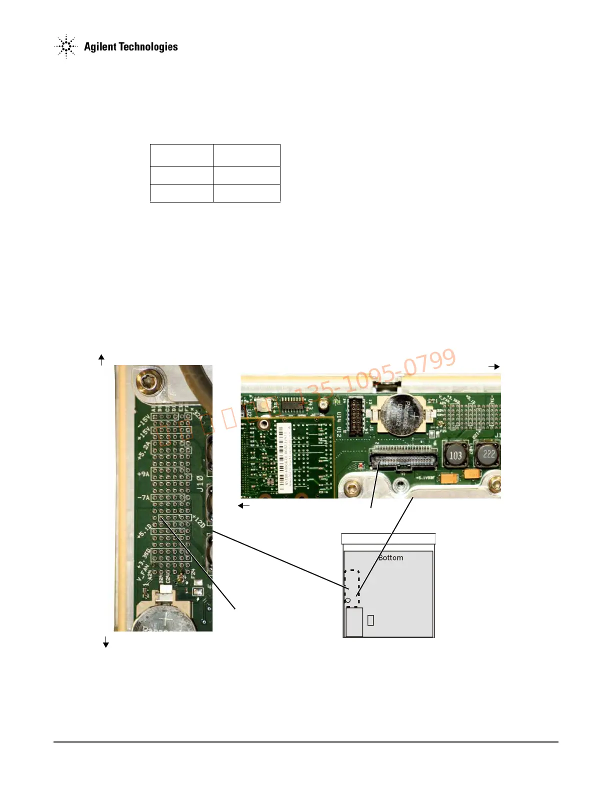
8. Refer to Figure 1-11. Using the voltmeter measure A3J6-3.
• If A3J6-3 is ∼12V replace the W1 ribbon cable.
• If A3J6-3 is not ∼12V go to step 9.
Figure 1-11 A3J6-3 and A3J10-B16
Table 1-4
Connector Voltage
J5-3 +11V
J5-4 (pwm_pic) >+1.3V
A3J6-3
A3J10-B16
Front Panel
Rear Panel
Rear Panel
Front Panel