Agilent Technologies N5161A/62A/81A/82A/83A MXG Signal Generators Service Guide
Post-Repair Procedures and Performance Verification
Leveled Output Power Verification (N5161A/62A
1
/81A/82A Only)
4-14
7. Set the amplitude to 13
1
dBm:
Press
Amplitude > 13 > dBm.
8. Configure the power meter for the measurement.
a. Press the
Frequency Cal Fac button on the power meter.
b. Select a power meter channel (if applicable).
c. Use the arrow keys to enter the frequency at which to measure the power.
9. Measure the output power level.
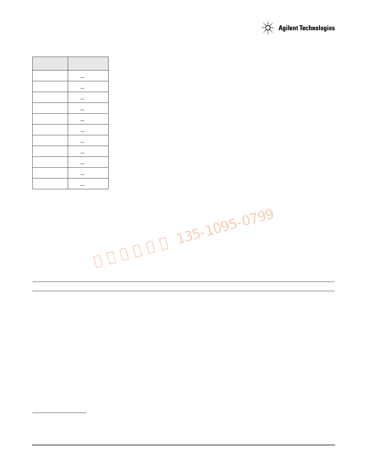
10. Repeat steps 6 through 9 to measure power at each of the 15 frequencies listed in Table 4-10.
11. Confirm that the measured power levels are within the limits listed in the table.
NOTE The limit range is due to power meter uncertainty.
538 MHz < 0.6dB
675 MHz <
0.6dB
850 MHz <
0.6dB
1075 MHz <
0.6dB
1350 MHz <
0.6dB
1700 MHz <
0.6dB
2150 MHz <
0.6dB
2700 MHz <
0.6dB
3400 MHz <
0.7dB
4300 MHz <
0.8dB
5400 MHz <
0.8dB
1
For serial numbers <MY4818xxxx, US4818xxxx, and SG4818xxxx, the amplitude = 7 dBm.
Table 4-10Leveled Output Power Limits (Continued)
Frequency Limits (dB)