Overview 1
N9342C/43C/44C User’s Guide 7
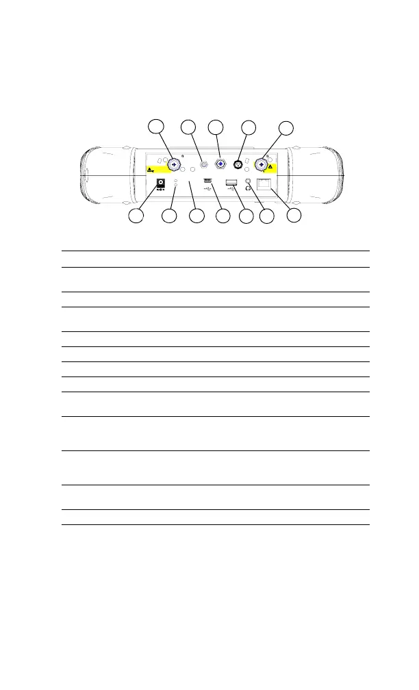
Top Panel Overview
Ext Powe r
Charging
PC
Ext Trig/
RF Out 50
Antenna
GPS
Probe
Pow er
Ext Ref
12-16
VDC
55
W MAX
RF Input 50
50 VDC M AX
30dBm (1W) M AX
50 VDC MAX
REV
PWR
30dBm (1W ) M AX
LAN
1
2
10
3
4
5
7
8
12
6
9
11
Items Function
1External DC power
connector
Provides input for the DC power source via an
AC-DC adapter, or Automotive type DC adapter.
2 LED indicator (Charging) Lights (On) when the battery is charging
3 LED indicator Lights (On) when external DC power is con-
nected.
4 USB interface (Device) Connects to a PC
5 USB interface (Host) Connects to a USB memory stick or disk
6 Headphone Connects to a headphone
7 LAN Interface Connects to a PC for SCPI remote control
8 RF OUT Connector The output for the built-in tracking generator.
Enabled with Option TG7.
9 Probe power connnector Provides power for high- impedance AC probes
or other accessories (+15 V, –12 V, 150 mA maxi-
mum).
10 EXT TRIG IN/REF IN
(BNC, Female)
Connects to an external TTL signal or a 10 MHz
reference signal. The TTL signal is used to
trigger the analyzer’s internal sweep
11 GPS antenna connector Connects an GPS Antenna (option GPA) for GPS
application.
12 RF IN Connector (50 Ω) Accepts an external singal input.