Functions and Measurements 3
N9342C/43C/44C User’s Guide 43
Making Distortion Measurements
This section provides information on measuring
and identifying signal distortion.
Identifying Analyzer Generated Distortion
High level input signals may cause analyzer
distortion products that could mask the real
distortion present on the measured signal. Use
trace and the RF attenuator to determine which
signals, if any, may be internally generated
distortion products.
In this example, a signal from a signal generator is
used to determine whether the harmonic distortion
products are generated by the analyzer.
1 Input a signal (200 MHz, –10 dBm) to the ana-
lyzer RF IN connector.
2 Set the analyzer center frequency and span:
• Press [Preset] (factory preset)
• Press [Freq] > 400 > {MHz}
• Press [Span] > 700 > {MHz}
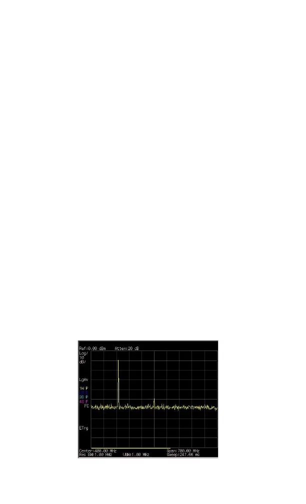
The signal produces harmonic distortion products
(spaced
200 MHz from the original 200 MHz signal).
Figure 3-13 Harmonic distortion