Functions and Measurements 3
N9342C/43C/44C User’s Guide 53
Making a Reflection Calibration
The following procedure makes a reflection
calibration using a coupler or directional bridge to
measure the return loss of a filter. This example
uses a 370 MHz low- pass filter as the DUT. The
tracking generator (option TG7) is needed for this
measurement. For N9342C handheld spectrum
analyzer with option CA7 or CAU, please refer to
the “Measuring Cable Reflection" on page 77 to
make a reflection measurement.
The calibration standard for reflection calibration
is usually a short circuit connected at the reference
plane (the point at which the DUT is connected). A
short circuit has a reflection coefficient of 1 (0 dB
return loss). It reflects all incident power and
provides a convenient 0 dB reference.
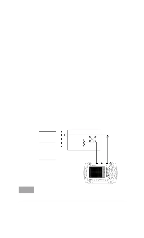
1 Connect the DUT to the directional bridge or
coupler as shown below. Terminate the
unconnected port of the DUT.
Figure 3-20
Reflection Measurement Short Calibration Test Setup
N9340A
HANDHELD SPECTRUM ANALYZER
100 kHz - 3.0 GHz
PRESET
ENTER
FREQ SPANAM PTD
BW/
SWP
SYS M ODE MEAS TRACE
ESC/CLR
2DEF 3 GHI1ABC
5MNO4JKL
6
PQR
8VWX7STU 9 YZ_
0SAV E
LIMIT
MARKER
Coupled Port
Short
Circuit
DUT
or
2 Connect the tracking generator output of the
analyzer to the directional bridge or coupler.
NOTE
If possible, use a coupler or bridge with the correct test port
connector types for both calibrating and measuring. For the
best results, use the same adapter for the calibration and the
measurement. Terminate the second port of a two port device.