3 Functions and Measurements
52 N9342C/43C/44C User’s Guide
8 Reconnect the DUT to the analyzer. Note that the
units of the reference level have changed to dB,
indicating that this is now a relative measure-
ment.
9 To change the normalized reference position:
Press [MEAS] > {Normalize} > {Norm Ref Posn} > 8 >
[ENTER]
10Place the reference marker at the specified cut-
off frequency:
Press [MARKER] > {Mode} > {Normal} > 370 > MHz
11 Set the 2nd marker as a delta frequency of
37
MHz:
Press {Delta} > 37 > MHz
12In this example, the attenuation over this
frequency range is 19.16 dB/octave (one octave
above the cutoff frequency).
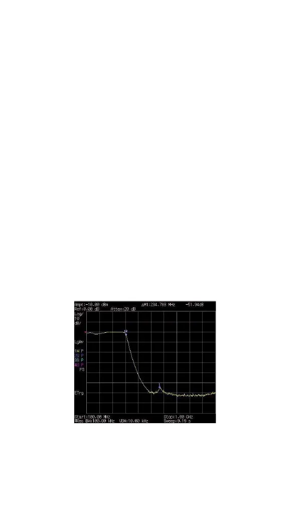
13Use the front- panel knob to place the marker at
the highest peak in the stop band to determine
the minimum stop band attenuation. In this
example, the peak occurs at 600 MHz. The
attenuation is 51.94 dB.
Figure 3-19Minimum Stop Band Attenuation