28 Power Mower 5400 Edition 02.97
3. Devices and Operating Elements
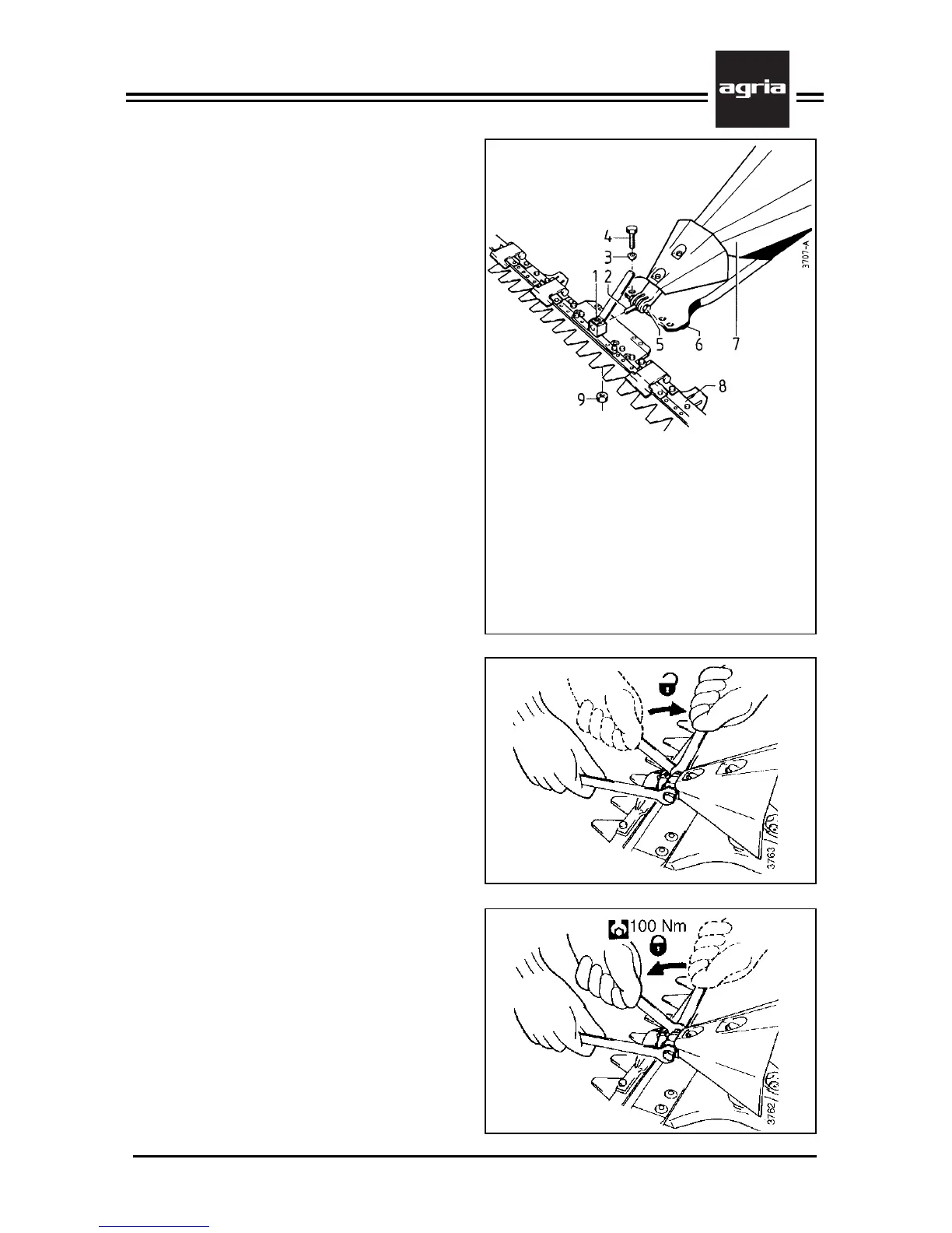
Figure K
1 Knife driver
2 Link pin
3 Ball spring ring
4 Hex head bolt
5 Clamping screw which holds the link pin
6 Cutter bar carrier
7 Mower hood
8 Cutter bar
9 Hex nut (locking nut)
only on version ”Universal SC”
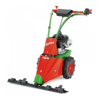
Rocker Arm Mowing
Attachment
Cutter Bar Attachment
W
Stop the engine, remove
spark plug connector! Wear
safety gloves!
l
Loosen clamping screw (K/5) so the
link pin can move up and down.
l
Attach the cutter bar to the cutter bar
carrier by aligning the link pin (K/2) in
the knife driver’s (K/1) hole.
l
Attach the cutter bar to the cutter bar
carrier using 4 hex head bolts (K/4) and
4 ball spring rings (K/3).
l
Tighten all 4 bolts evenly at 70 Nm.
l
For Universal-SC cutter bar attach-
ment, additionally lock the attachment
bolts (K/4) with hex nuts (K/9) under the
cutter bar’s bottom.
Tighten the clamping screw which holds
the link pin (K/5) at 100 Nm.
For cutter bar removal reverse this or-
der. As a first step, loosen the clamping
screw which holds the link pin so this
can move up and down.
For cutter bar accessories see page 63.