Mounting/exchanging the upper link extension
You can install an upper link of long design (agria art.-no. 9740 111) on the 9700e.
The hydraulic lines are pressurised. Hydraulic oil could leak when uncoupling the upper link.
Pay attention that the upper link is depressurised during the exchange. If a mounted implement is attached,
place it on the ground. Adjust the length of the upper link so that both ball joint bearings at the ends of the
upper link are no longer under tension. The hydraulic lines are depressurised and can be easily discon-
nected from the hydraulic connections. If no mounted implement is attached, the upper link is also depres-
surised. Inverting the connections will lead to the functions being reversed.
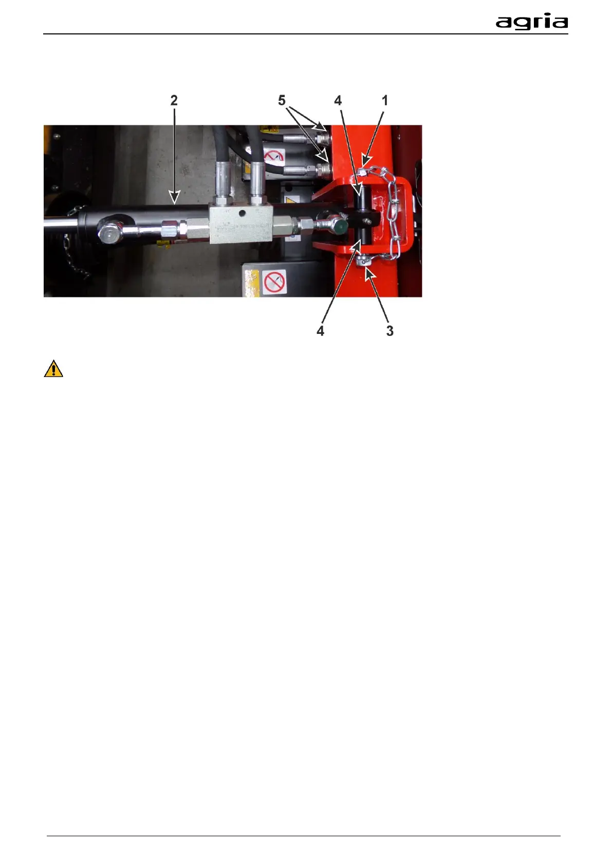
1. Uncouple the hydraulic lines from the base unit.
2. Dismantle the upper link (2) from the mounted implement.
3. Open the lynch pin (1).
4. Pull the bolt (3).
5. Remove the sleeves (4).
6. You can now mount the other upper link in reverse order.