SmartyCam
User Manual
Release 1.04
24
www.smartycam.com
11
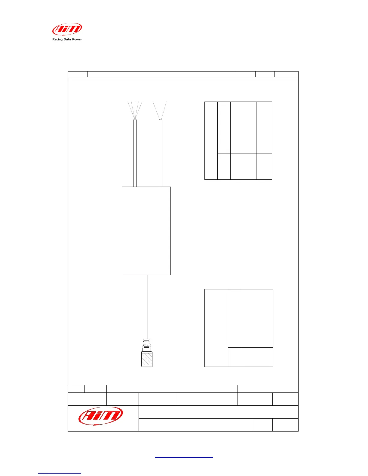
Appendix “D” – ECU Bridge Pinout
WHITE
WHITE
BLACK
BLACK
RED
Materiale / MaterialQ.tà / Q.tyRif. / Ref.
Progettato da / Designed by Contr. da / Ckd. by
Approvato da / Approved by
Nome file / File name
Data / Date
N. articolo / Item N.
Scala / Scale
Foglio / SheetRev. / Rev.
Titolo / Title
N. disegno / Drawing N.
N.rev. / Rev. N.
Descrizione / Description
Data / date
Firma / Sign
Contr. da / Ckd. by
Racing Data Power
L.I.
Collegamento cavi SmartyCam -ECU Bridge protocollo CAN/RS232
1 of 1
Pinout of ECU Bridge for SmartyCam: CAN/RS232 protocol
5 pins Binder 712
female connector
5 pins Binder 712
female connector pinout
contact insertion view
Pin
Fonction
1
2
3
4
5
CAN+
GND
+Vb
CAN-
Vbext
Not terminated cables pinout
Cable colour
Fonction
White
Blue
Black
Blue
White
CAN1+
CAN1-
GND
RS232TX
RS232RX
NOT TERMINATED CABLES
ECU BRIDGE
BLUE
BLUE
GND
+Vbext
Black
Red