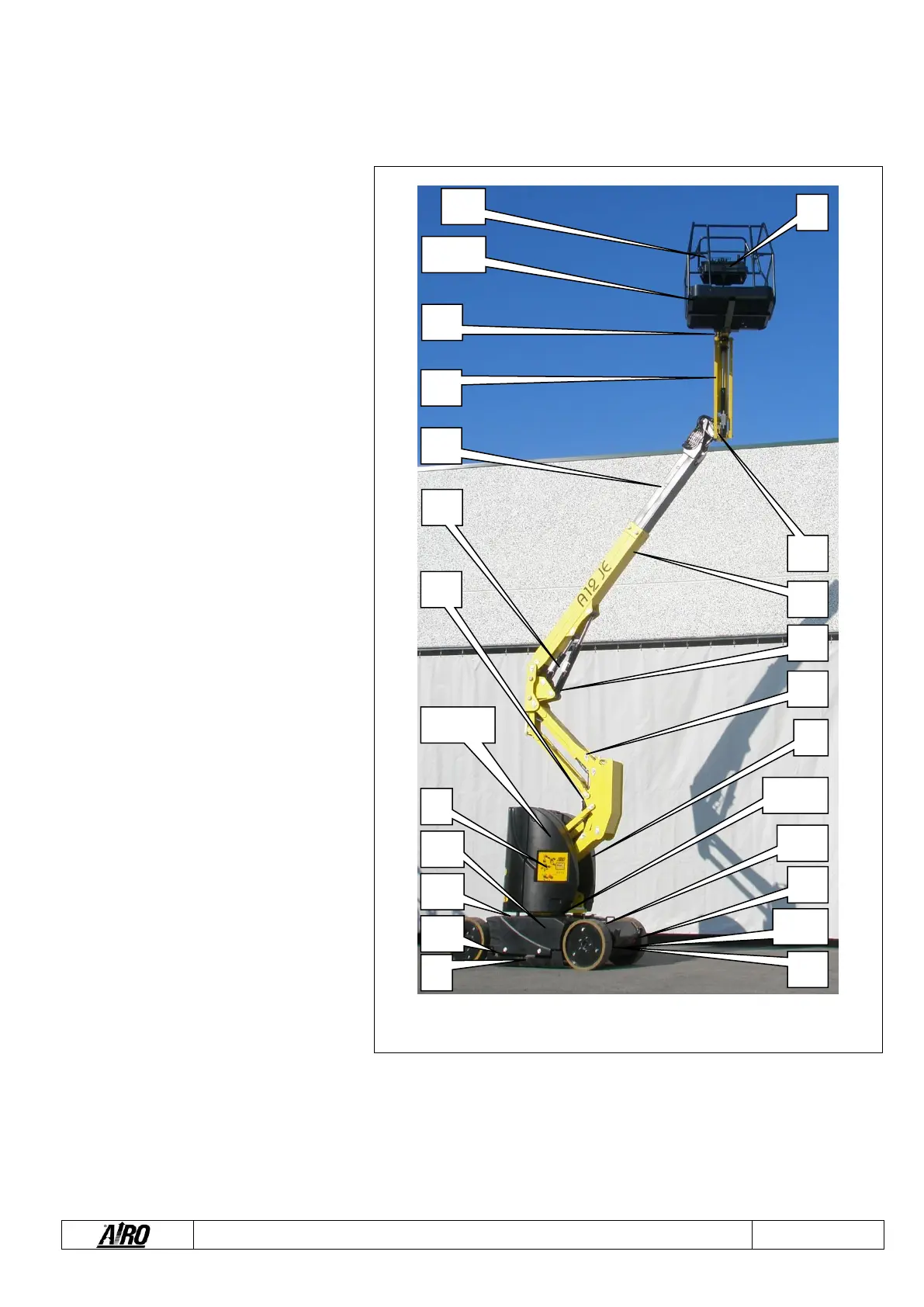
1) Control panel
2) Ground emergency controls
3) Electric control unit
4) Hydraulic oil tank
5) Diesel tank (models ED)
6) Diesel motor generator (models ED)
7) Pot-hole guards;
8) Electric pump
9) Electric drive motors with brake;
10) Turret rotation hydraulic motor;
11) 230V plug (optional)
12) Spirit level (optional) for visual check of
machine levelling
13) Lifting cylinders
14) Battery
15) (Optional) electric line plug
16) Inclinometer;
17) Limiting sensor of platform load (load
cell)
18) Fifth wheel coupling and proximity
sensors PS1A-PS1B (only for A17 JE);
19) Drive motors AC controllers and
electric pump
20) Battery charger power supply plug;
21) Microswitch M1A
22) Microswitch M1B
23) Microswitch M1C
24) Microswitch M1E and microswitch M1S
(only for A17 JE with ROTATING JIB);
25) Microswitches MPT1-MPT2
26) Microswitches M2A-M2B;
27) “AIRO SENTINEL” anti-trapping
system - OPTIONAL.