1.3.1. Leaving at height
The work elevating platforms are not designed by taking into account the risks of the “leaving at height” because the only access
position considered is when the platform is completely lowered. For this reason, this activity is formally forbidden.
However, there are exceptional conditions in which the operator needs to access or leave the work platform not in the access
position. This activity is normally defined as “leaving at height”.
The risks connected to the “leaving at height” do not depend exclusively on the PLE (work elevating platform) characteristics; a
specific risk analysis carried out by the employer can authorize this specific use by taking into account:
▪ The working environment characteristics;
▪ The absolute prohibition to consider the work platform as an anchoring point for people working outdoors;
▪ The use of the machine at xx% of its performances to avoid that additional forces created by a specific operation or
bending of the structure move away the access zone from the unloading zone. Provide for some tests in order to define
these limitations;
▪ Provide for a specific evacuation procedure in case of emergency (for example: an operator always on the platform, one at
the ground control panel while a third operator leaves the lifted platform);
▪ Provide for a specific training of the staff both as operator and transported staff;
▪ Equip the unloading zone with all the devices that are necessary to avoid the risk of fall of the staff that accesses/leaves
the platform.
What said above is not a formal authorization of the manufacturer for the “leaving at height”, but it wants to supply information to
the employer - who is fully responsible for that - which can be useful for the planning of this exceptional activity.
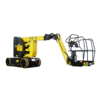
1.4. Description of the machine
The machine described in this use and maintenance manual is a self-propelled Elevating Work Platform equipped with:
▪ motorized chassis equipped with wheels;
▪ hydraulically driven rotating turret;
▪ Articulated boom operated by hydraulic cylinders (the number of articulations and cylinders varies according to machine
model).
▪ operator platform (the max. capacity varies according to the model - see chapter "Technical features”).
The chassis is motorised to allow the machine to move even with lifted platform (see "Use instructions”) and has two rear driving
wheels and two front idle steering wheels. The rear wheels are equipped with parking brakes, positive logic type (when drive
controls are released brakes are automatically activated). On the chassis there are two pot-hole guards automatically activated by
the platform control panel (depending on the rotating turret position) when the platform is raised.
The turret rests on a turntable fixed to the chassis and can be oriented (rotated) by 370° non-continuous around the central axle of
the machine by means of irreversible endless screw.
The lifting system, with articulated boom, can be divided into three main structures:
▪ The first, with vertical extension, consists of a “double parallelogram” system named “pantograph”.
▪ The second, consists of a lifting boom with telescopic extension.
▪ The third, consists of a terminal boom called "Jib" (the Jib is fixed as a standard, as an option it is rotating of about 130°
totally).
The hydraulic cylinders which move the articulated structure are provided with over-center valves directly flanged on the same.
These devices allow the booms to remain in position even if one of the supply tubes accidentally breaks.
The platform, hinged to the end of the “jib”, can be rotated by 180° totally (90° on the right and 90° on the left) by means of a
rotary actuator fitted with over-centre valve. It is fitted with rails and toe boards of prescribed height (the rails height 1100 mm; the
toe boards height 150 mm; in the access area the toe board height is 100 mm). The platform levelling is automatic and is
ensured by mechanical ties and two cylinders in closed circuit. The manual level compensation is possible by acting on the relevant
control only with completely lowered booms (and with “Jib” inclination ranging between +10° and –70° with respect to the horizontal
axis).