ZYNQ FPGA Development Board AX7021 User Manual
l
Amazon Store: https://www.amazon.com/alinx
can be connected to the USB port of the upper PC with a USB cable for
separate power supply and serial data communication of the core board.
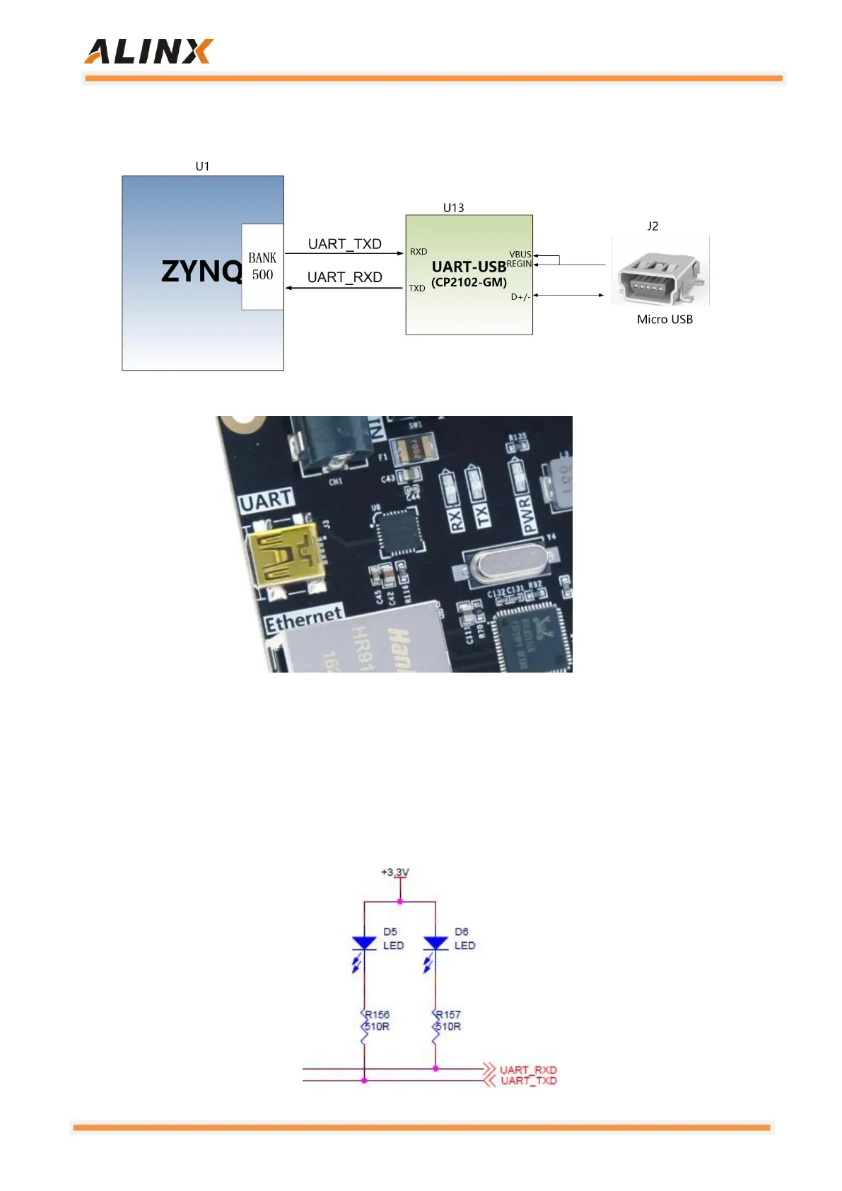
Figure 2-7-1: USB to Serial Port
Figure 2-7-2: USB to Serial Port on the Core Board
At the same time, two LED indicators are set on the serial port signal, and
the LEDs on the PCB are printed as RX and TX LEDs (D5 and D6). The RX
and TX LEDs indicate whether the serial port has data received or sent, as
shown in the Figure 2-7-3 below.
Figure 2-7-3: USB to serial port signal indicator