ZYNQ FPGA Development Board AX7021 User Manual
l
Amazon Store: https://www.amazon.com/alinx
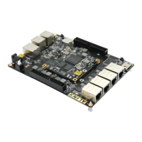
Figure 3-8-2: LED on the Carrier Board
Pin Assignment:
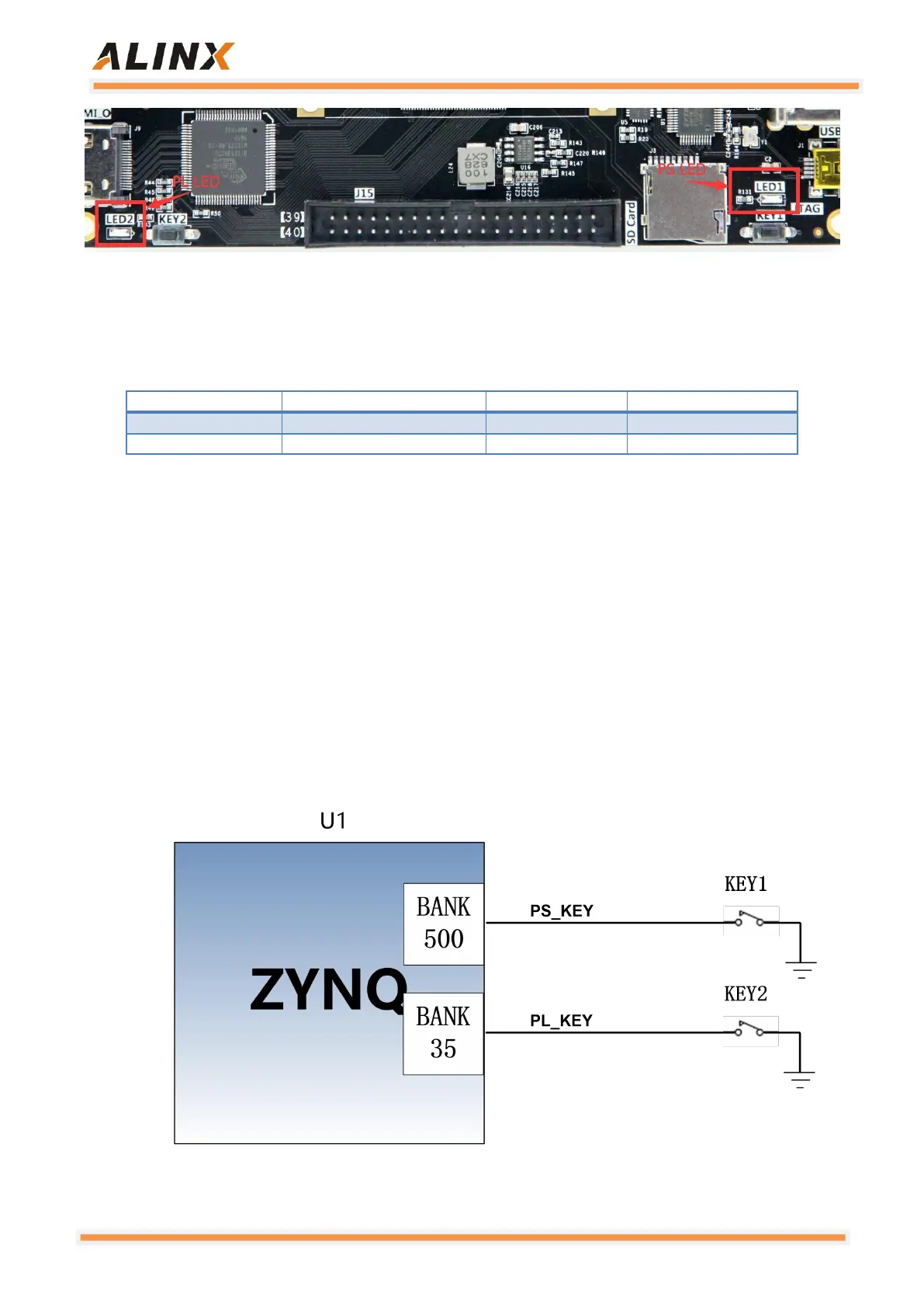
3.9 User Button
The AX7021 has two user buttons KEY1 and KEY2 on the carrier board.
KEY1 is connected to the MIO pin of the ZYNQ chip PS, and KEY2 is
connected to the IO pin of the ZYNQ chip PL. When the button is pressed, the
signal is low, and the ZYNQ chip detects a low level to determine whether the
button is pressed. The schematic diagram of the user button connection is
shown in Figure 3-9-1:
Figure 3-9-1: The Schematic Diagram of the User Button