ZYNQ FPGA Development Board AX7021 User Manual
l
Amazon Store: https://www.amazon.com/alinx
Uart Pin Assignment:
Table 2-7-1: Uart Pin Assignment
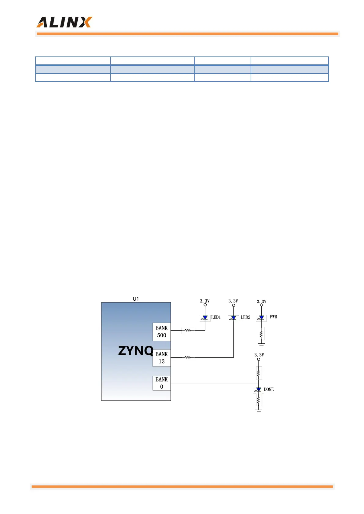
2.8 LED
There are 6 red LED lights on the AC7021 core board, one of which is the
power indicator light (PWR), one is the configuration LED light (DONE), two are
the user LED lights (LED1~LED2), and the other two are the UART transmit
and receive indicators (TX, RX). When the core board is powered, the power
indicator will illuminate; when the FPGA is configured, the configuration LED
will illuminate. Two user LED lights are connected to the MIO of the PS, one is
connected to the IO of the PL, the user can control the lighting and off by the
program, when the IO voltage connected to the user LED light is high, the user
LED light is off. When the connection IO voltage is low, the user LED will be
illuminated. The schematic diagram of the LED light hardware connection is
shown in Figure 2-8-1:
Figure 2-8-1: The schematic diagram of the LED light hardware connection