ZYNQ FPGA Development Board AX7021 User Manual
l
Amazon Store: https://www.amazon.com/alinx
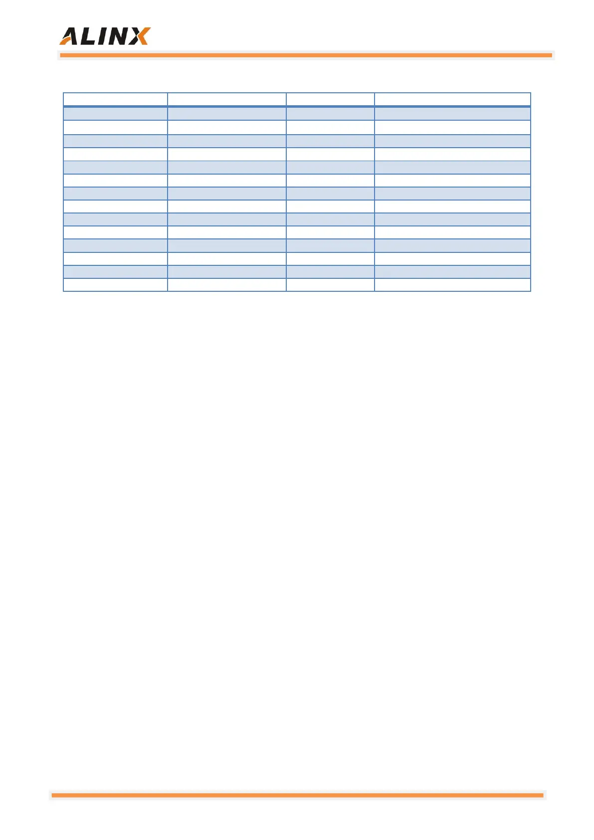
ETH4(PL) Pin Assignment:
Receive data valid signal
3.3 USB2.0 Host interface
There are 4 USB2.0 HOST interfaces on the AX7021 carrier board. The
USB2.0 transceiver uses a 1.8V, high-speed USB3320C-EZK chip that
supports the ULPI standard interface, and then expands the 4-port USB HOST
interface through a USB HUB chip USB2514. ZYNQ's USB bus interface is
connected to the USB3320C-EZK transceiver to achieve high-speed USB2.0
Host mode data communication. The USB3320C's USB data and control
signals are connected to the IO port of the BANK501 on the PS side of the
ZYNQ chip. The USB interface differential signal (DP/DM) is connected to the
USB2514 chip to extend the four USB ports. Two 24MHz crystal oscillators
provide system clocks for the USB3320C and USB2514 chips, respectively.
The USB interface is a flat USB interface (USB Type A), which allows
users to connect different USB Slave peripherals (such as USB mouse and
USB keyboard) at the same time. The carrier board also provides +5V power to
each USB interface
The schematic diagram of the ZYNQ processor, USB3320C-EZK chip,
USB2514 chip connection is shown as Figure 3-3-1