ZYNQ FPGA Development Board AX7021 User Manual
l
Amazon Store: https://www.amazon.com/alinx
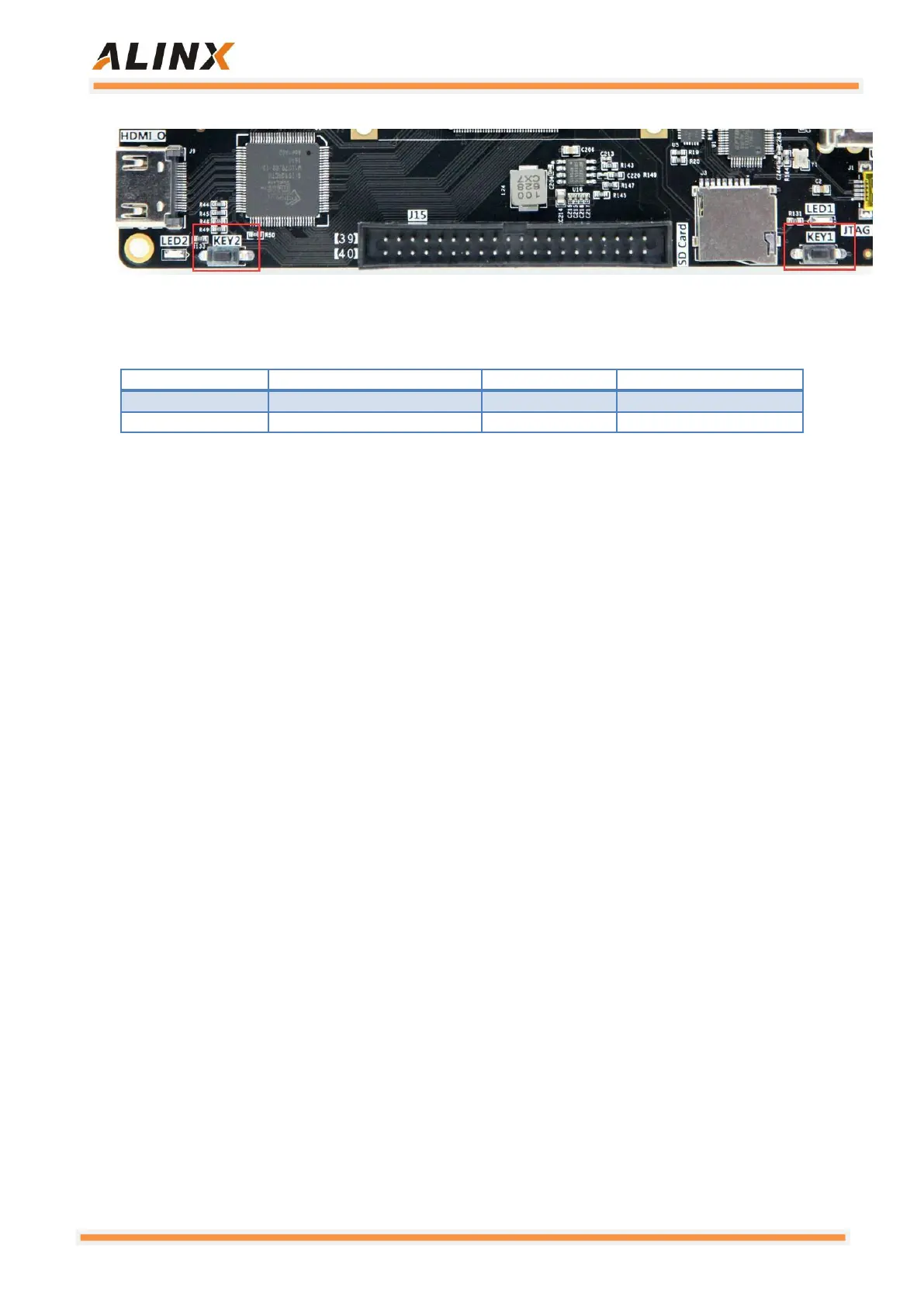
Figure 3-9-2: The User Button on the Carrier Board
Pin Assignment:
3.10 Extension Port
The AX7021 carrier board is reserved with two 2.54-mm standard 40-pin
expansion ports J15 and J16 for connecting various modules of ALINX or
external circuits designed by the user. The expansion port has 40 signals, of
which 1 channel is 5V power supply. 2 channels are 3.3V power supplies, 3
Ground, 34 IOs. Do not connect the IO directly to a 5V device to avoid
burning the ZYNQ7000 chip. If you want to connect a 5V device, you need
to connect a level shifting chip.
A 33 ohm resistor is connected in series between the expansion port and
the ZYNQ7000 connection to protect the ZYNQ7000 chip from external voltage
or current. The circuit of the expansion port (J15) is shown in Figure 3-10-1.