ZYNQ FPGA Development Board AX7021 User Manual
l
Amazon Store: https://www.amazon.com/alinx
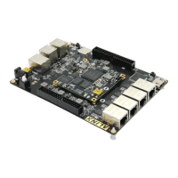
3.11 Power Supply
The power supply input voltage of the development board is DC12V. The
carrier board is converted into +5V, +1.2V, +3.3V and 1.8V four-way power
supply through one DC/DC power chip MP2303 and three DC/DC power chip
MP1482. Because the +5V power supply supplies power to the core board
through the inter-board connector, the current output of the DC power supply is
3A, and the output current of the other three power supplies is 2A. In addition,
there is an LDO chip on the board. The default output is 3.3V. If the BANK
power of BANK33 and BANK34 of the core board is replaced with other voltage
levels, the output of this LDO chip on the carrier board needs to be modified
accordingly.
The power supply design on the carrier board is shown below