Amazon Store: https://www.amazon.com./alinx
Sales Email: rachel.zhou@aithtech.com
ARTIX-7 FPGA Development Board AX7035 User Manual
Figure 13-2: USB to serial port on the FPGA Board
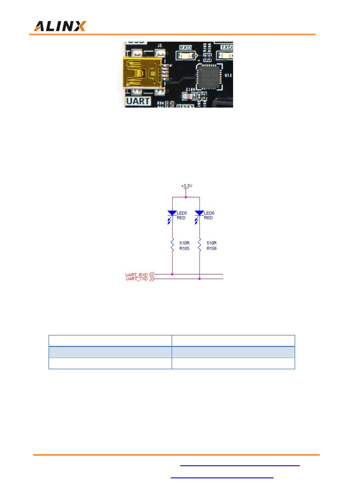
Two LED indicators (LED5 and LED6) are set for the serial port signal, and
the silkscreen on the PCB is TX and RX, indicating that the serial port has data
transmission or reception, as shown in the following Figure 13-3
Figure 13-3: Serial Port communication LED Indicators Schematic
USB to serial port pin assignment:
Part 14: EEPROM 24LC04
The AX7035 development board contains an EEPROM, model 24LC04,
and has a capacity of 4Kbit (2*256*8bit). It consists of two 256-byte blocks and
communicates via the IIC bus. The onboard EEPROM is to learn the