Amazon Store: https://www.amazon.com./alinx
Sales Email: rachel.zhou@aithtech.com
ARTIX-7 FPGA Development Board AX7035 User Manual
Part 21: LED Light
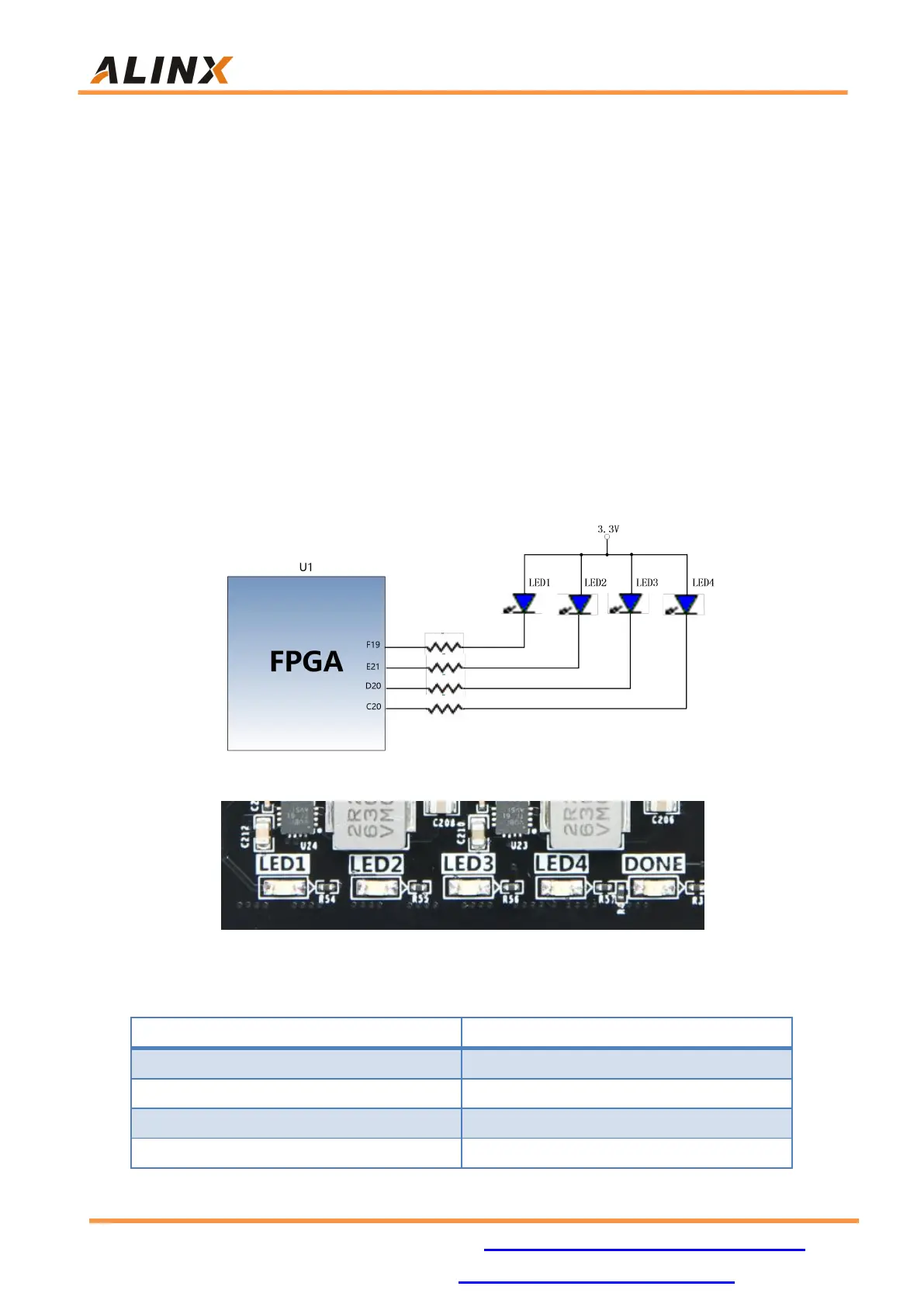
There are seven red LEDs on the AX7035 FPGA development board, one
of which is the power indicator (PWR), two are USB Uart data receiving and
sending indicators, four are users LED lights (LED1~LED4). When the AX7035
FPGA board is powered on, the power indicator will light up; User LED1~LE4D
are connected to the normal IO of the FPGA. When the IO voltage connected
to the user LED is configured low level, the user LED lights up. When the
connected IO voltage is configured as high level, the user LED will be
extinguished. The schematic diagram of the user LEDs hardware connection is
shown in Figure 21-1.
Figure 21-1: The User LEDs Schematic
Figure 21-2: The User LEDs on the FPGA Board
Pin assignment of user LED lights