Amazon Store: https://www.amazon.com./alinx
Sales Email: rachel.zhou@aithtech.com
ARTIX-7 FPGA Development Board AX7035 User Manual
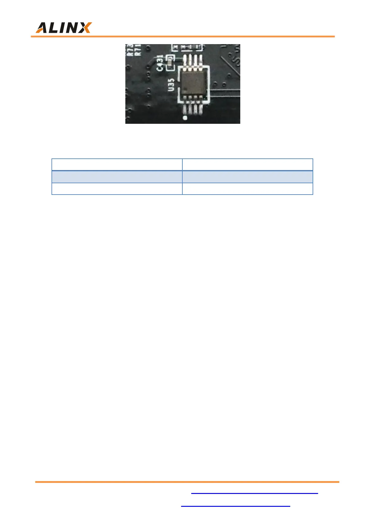
Figure 16-2: LM75 Sensor on the FPGA Board
LM75 Sensor Pin Assignment
Part 17: Expansion Header
The AX7035 FPGA development board is reserved with two 0.1inch
spacing standard 40-pin expansion headers J9 and J10. Which are used to
connect the ALINX modules or the external circuit designed by the user.The
signal of the expansion port J9 is connected to the BANK16 of the FPGA, so
the LDO chip (U27) can be replaced to meet different level’s standard. The IOs
of J10are connected to the BANK14 of the FPGA, so the IOs of J10 level
standard is fixed at 3.3V.
The expansion port has 40 signals, of which 1-channel 5V power supply,
2-channel3.3 V power supply,3-channle ground and 34 IOs. Do not directly
connect the IO directly to the 5V device to avoid burning the FPGA. If you
want to connect 5V equipment, you need to connect level conversion
chip.
A 33 ohm resistor is connected in series between the expansion port and
the FPGA connection to protect the FPGA from external voltage or current. The
circuit of the expansion port (J9) is shown in Figure 17-1