Amazon Store: https://www.amazon.com./alinx
Sales Email: rachel.zhou@aithtech.com
ARTIX-7 FPGA Development Board AX7035 User Manual
Part 7: QSPI Flash
The AX7035 FPGA development board is equipped with one128MBit
QSPI FLASH, and the model is N25Q128, which uses the 3.3V CMOS voltage
standard. Due to the non-volatile nature of QSPI FLASH, it can be used as a
boot device for the system to store the boot image of the system. These
images mainly include FPGA bit files, ARM application code, core application
code and other user data files. The specific models and related parameters of
QSPI FLASH are shown in Table 7-1.
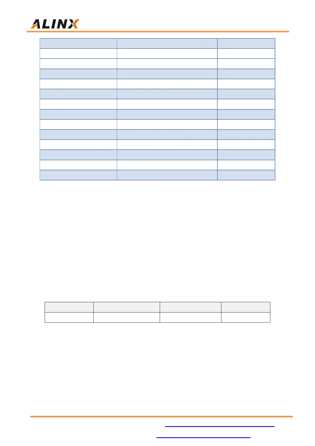
Table 7-1: QSPI FLASH Specification
QSPI FLASH is connected to the dedicated pins of BANK0 and BANK14 of
the FPGA chip. The clock pin is connected to CCLK0 of BANK0, and other data
and chip select signals are connected to D00~D03 and FCS pins of BANK14
respectively. Figure 7-1 shows the hardware connection of QSPI Flash.