Chapter 2
Installation/Wiring
2–22
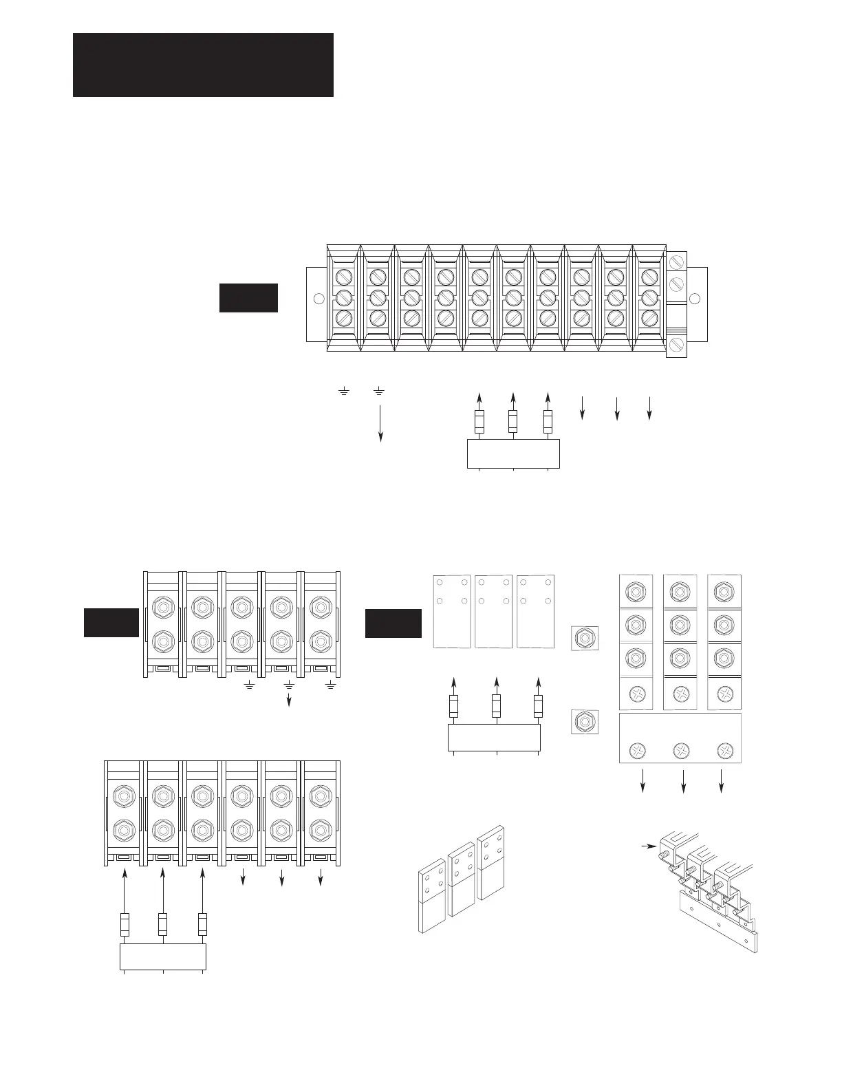
Figure 2.10.
Terminal Block TB1 cont.
PE
GRD
PE
GRD
DC
+
Dynamic Brake
Required
1
Input Fusing
DC
–
R
(L1)
S
(L2)
T
(L3)
W
(T3)
U
(T1)
V
(T2)
To Motor
AC Input Line
200–240V, 15–22 kW (20–30 HP) Terminal Designations
380–480V, 30–45 kW (40–60 HP) Terminal Designations
500–600V, 18.5–45 kW (25–60 HP) Terminal Designations
1
Required Branch
Circuit Disconnect
C Frame
To Motor
PE PEDC +
Brake
1
Required
Input Fusing
DC –
Brake
R
(L1)
T
(L3)
W
(T3)
U
(T1)
V
(T2)
To Motor
AC Input Line
200–240V, 30–45 kW (40–60 HP) Terminal Designations
380–480V, 45–112 kW (60–150 HP) Terminal Designations
500–600V, 56–112 kW (75–150 HP) Terminal Designations
1 Required Branch
Circuit Disconnect
TE
S
(L2)
To Motor
DC +
Brake
380–480V, 224–448 kW (300–600 HP) Terminal Designations
500–600V, 187–485 kW (250–650 HP) Terminal Designations
To Motor
DC –
Brake
Required
1
Input Fusing
AC Input Line
W
(M3)
U
(M1)
V
(M2)
Brake terminals are located
behind the “U” terminal.
Access terminals
from side of chassis
(located at bottom of drive)
W
U
V
1
Required Branch
Circuit Disconnect
R
(L1)
S
(L2)
T
(L3)
typical terminal layout
(located at top of drive)
R
S
T
D Frame
G Frame

 Loading...


