Chapter 2
Installation/Wiring
2–23
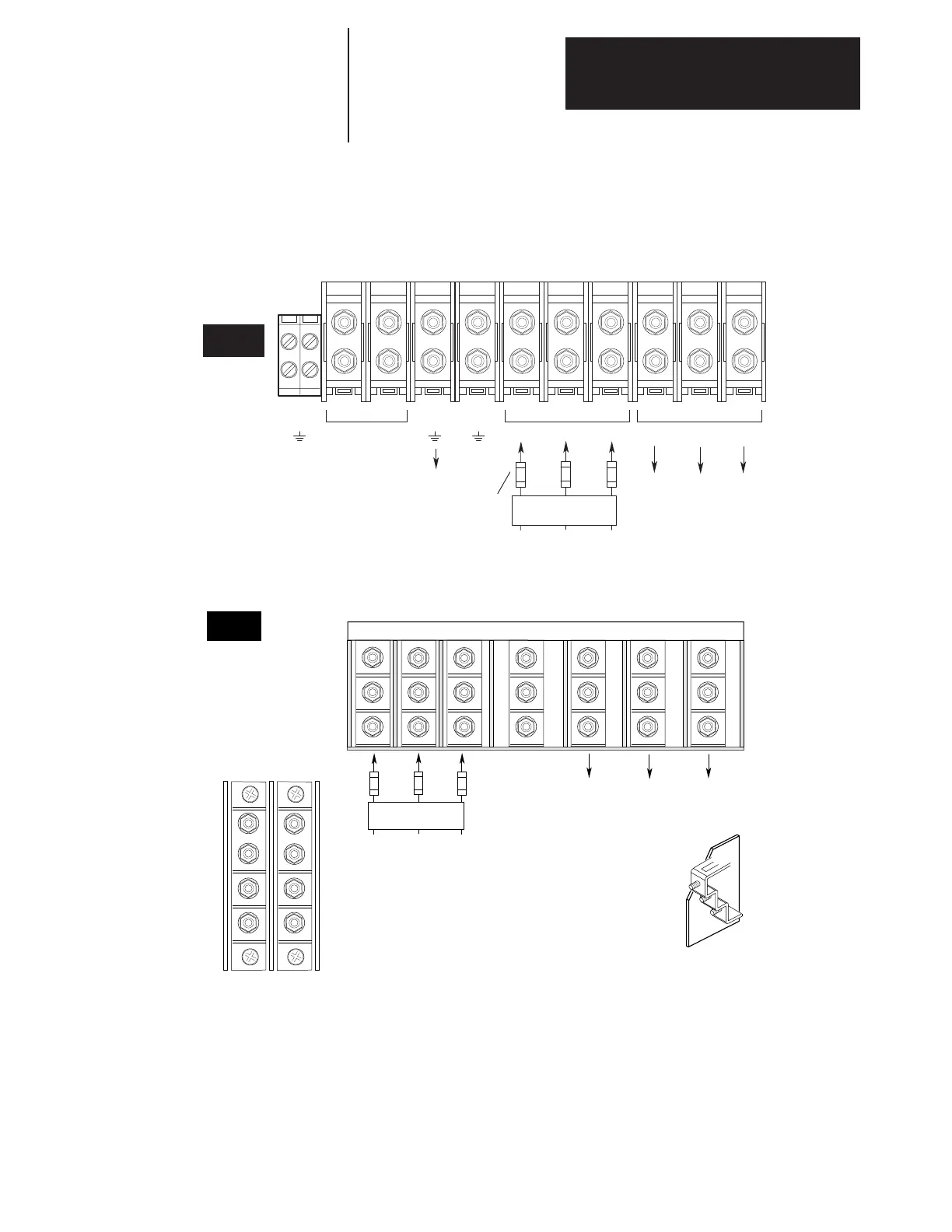
Figure 2.10. cont.
Terminal Block TB1
200–240V, 56–75 kW (75–100 HP) Terminal Designations
380–480V, 112–187 kW (150–250 HP) Terminal Designations
500–600V, 112–149 kW (150–200 HP) Terminal Designations
TE
BUS INPUT OUTPUT
– DC
+DC
PE PE R–L1 S–L2 T–L3 U–M1 V–M2 W–M3
Required
1
Input Fusing
To Motor
AC Input Line
1 Required Branch
Circuit Disconnect
To Motor
E Frame
typical terminal
380-480V, 187-336 kW (250-450 HP) Terminal Designations
To Motor
T-L3
R-L1
S-L2
W-M3
U-M1PE
V-M2
F
Frame
Input Fusing
(Supplied)
AC Input Line
1
Required Branch
Circuit Disconnect
DC –
Brake
DC +
Brake

 Loading...


