158 Rockwell Automation Publication 1444-UM001D-EN-P - June 2018
Chapter 4 Measurement Definition
Calibration Units EU (0)
Volts(1)
Specifies the units for the Calibration Offset. When toggling between Volts and EU, the value of the Calibration Offset is converted
based on the selected Units (top of page) and the sensitivity that is defined on the HW Configuration page.
Calibration Offset -50,000…50,000 Thrust Position is calculated as:
Thrust Position = measured position + offset
See the text following the table for a further discussion of how to set the offset value.
Presented Value:
To simplify setting the offset for normal thrust measurements, the AOP presents the offset value differently than how the value is
stored in the configuration assembly, and communicated to the module (see Saved Value).
The AOP allows you to specify that the Offset is presented in Engineering Units or Volts. Use the Calibration Units control to choose.
When in Volts, the value entered must always match precisely what is read by a common voltmeter if connected to the sensor,
including the values sign. When in EU, the value is always entered as a positive value.
• Regardless of the units of the entered Offset or the method that is used to determine the Offset, the goal is to set the DC Voltage
output of the tag to zero. After setting the calibration offset, the tag must be checked for the expected value at or near zero; note the
starting point of the measurement.
• In most cases thrust measurements are made using negatively biased, API-670 compliant, eddy current probes. Consequently the
Transducer High Limit must always be negative, to reflect the expected high value of the sensors bias.
• Positive bias probes can be used by making sure that the Transducer High Limit is set to a positive value and then verifying that the
sense control is set properly for the expected behavior.
IMPORTANT: The module requires that the voltage output from any positive bias probe increase as the probe moves away from the
target material.
Saved Value:
The Calibration Offset saved in the configuration assembly and communicated to the module is in the Engineering Units that are
specified at the top of the page. It is saved with its sign set as shown in the following table.
When a configuration is applied, if the Offset is in Volts, the AOP converts it to Engineering Units. The sign of the saved EU value is also
forced, based on the Sense Control.
In the above the Transducer High Limit, which is specified on the Hardware Configuration Page
, is used to determine if the bias of
sensor. All standard, API-670 compliant, eddy current probes are negative biased sensors.
Sense Control Away (0)
Toward (1)
The module uses this parameter for axial position and thrust measurements. Select the direction in which the target surface moves,
relative to the sensor, to cause a more positive displacement. The direction of a more positive displacement depends on the type of
installation. The module also uses this parameter for head-to-head type differential expansion measurements.
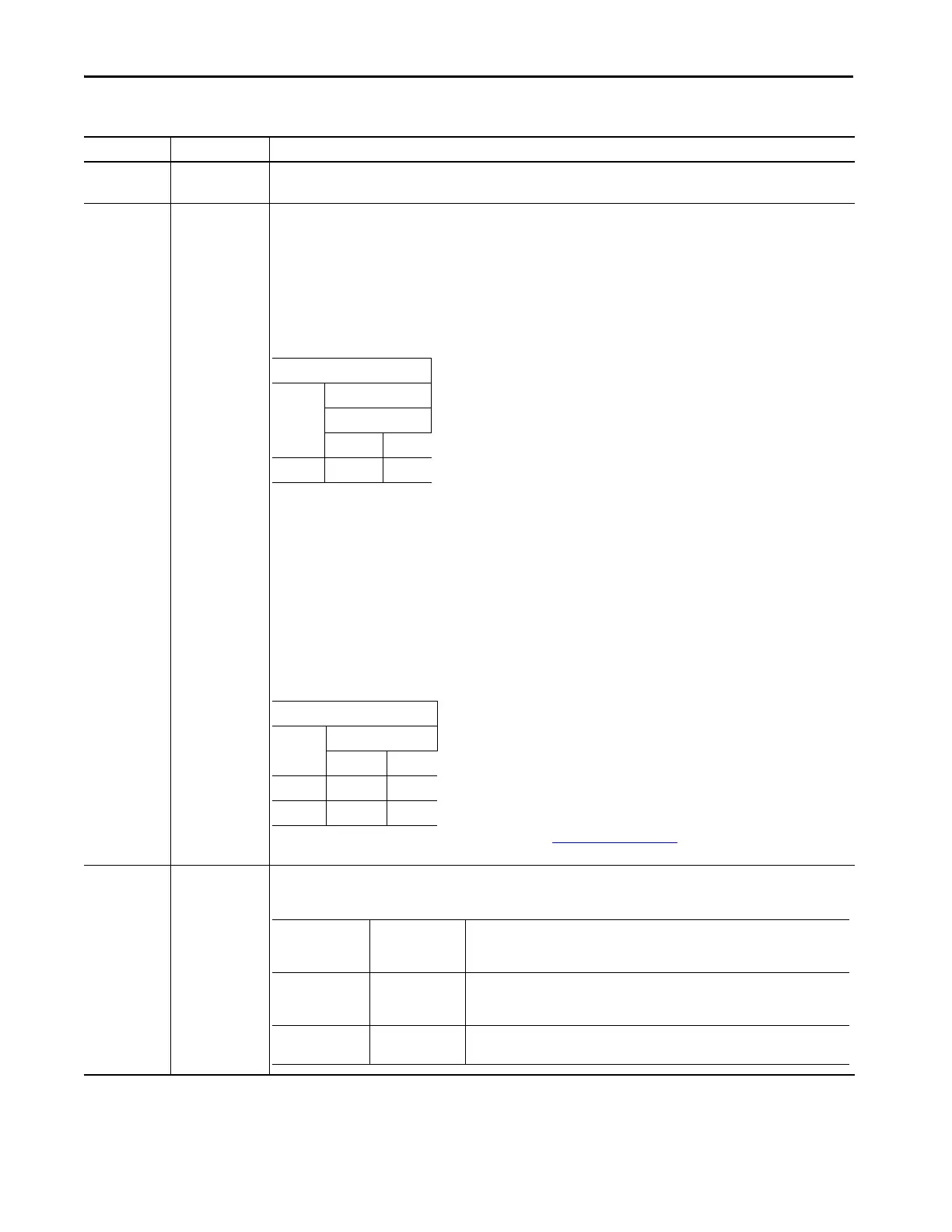
Table 33 - Configure Parameters for Normal Thrust Measurements (continued)
Parameters Values Comments
Presented Value
EU Volts
Xdcr High Limit
≤0 >0
positive negative positive
Saved Value in (EU)
Sense Xdcr High Limit
≤0 >0
Away negative positive
Toward positive negative
Installation Type Positive
Displacement
Direction
Description
Active/Normal Away Displacement is considered positive when the target moves away from probe. As the
target moves away from an eddy current probe (ECP), the system output becomes more
negative.
Inactive/Counter Toward Displacement is considered positive when the target moves toward the probe. In this
case, an ECP output becomes less negative.
 Loading...