68 Rockwell Automation Publication 1444-UM001D-EN-P - June 2018
Chapter 2 Install the Dynamix 1444 Series Monitoring System
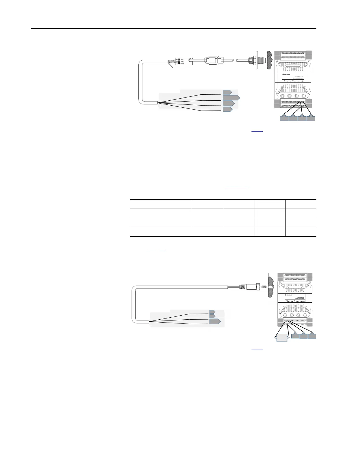
Figure 24 - Channel 3 Wiring
* Shield can be landed to any available shield connection. See the IMPORTANT note on page 56 for additional information.
2-wire Acceleration, Pressure, or Piezoelectric Velocity Sensors
The channel must be configured for a positive, constant current supply and the
transducer power output must be connected to the spare signal connection
(link terminals 1 and 2 in channel 0, see Figure 24
). A list of appropriate
terminals for each channel follows.
Figures 25
…28 show typical wiring for 2-wire constant current sensors
including IEPE Acceleration, Velocity, and Pressure Sensors.
Figure 25 - 2-wire IEPE Sensors Channel 0 Wiring
* Shield can be landed to any available shield connection. See the IMPORTANT note on page 56 for additional information.
Typical Core Designation Channel 0 Channel 1 Channel 2 Channel 3
SIG (+) 371115
Return (-) 481216
Then link these terminals: 1 and 2 5 and 6 9 and 10 13 and 14
Shield Floating
Driver
Common
Signal Output
Shield
-24V DC
16
14 or 15
31*
13
64
48
49
33
1
16
17
32
13
31
14
16
Pin A - Signal
Pin B - Common
Cable shield not
connected at this end
Common
Signal
Shield
4
19*
64
49
48
33
1
16
17
32
19
3
4
1 - 2
jumper
3

 Loading...