Rockwell Automation Publication 1444-UM001D-EN-P - June 2018 69
Install the Dynamix 1444 Series Monitoring System Chapter 2
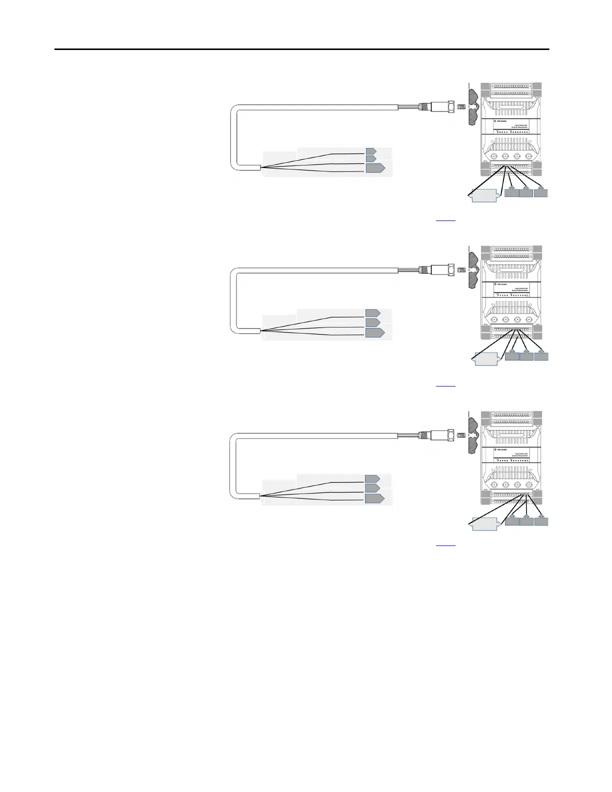
Figure 26 - 2-wire IEPE Sensors Channel 1 Wiring
* Shield can be landed to any available shield connection. See the IMPORTANT note on page 56 for additional information.
Figure 27 - 2-wire IEPE Sensors Channel 2 Wiring
* Shield can be landed to any available shield connection. See the IMPORTANT note on page 56 for additional information.
Figure 28 - 2-wire IEPE Sensors Channel 3 Wiring
* Shield can be landed to any available shield connection. See the IMPORTANT note on page 56 for additional information.
Pin A - Signal
Pin B - Common
Cable shield not
connected at this end
Common
Signal
Shield
8
23*
7
64
49
48
33
116
17
32
23 7 8
5 - 6
jumper
Pin A - Signal
Pin B - Common
Cable shield not
connected at this end
Common
Signal
Shield
12
27*
11
64
49
48
33
1
16
17
32
9 - 10
jumper
27
11
12
Pin A - Signal
Pin B - Common
Cable shield not
connected at this end
Common
Signal
Shield
16
31*
15
64
49
48
33
1
16
17
32
13 - 14
jumper
31
15 16
 Loading...