Rockwell Automation Publication 1444-UM001D-EN-P - June 2018 67
Install the Dynamix 1444 Series Monitoring System Chapter 2
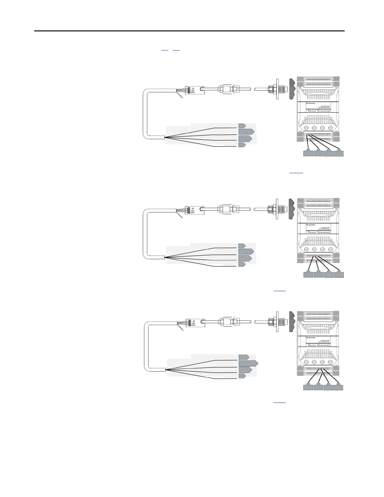
Figures 21…24 show typical wiring diagrams for channels 0…3 of an eddy
current probe sensor.
Figure 21 - Channel 0 Wiring
*Shield can be landed to any available shield connection. See the IMPORTANT note on page 56 for additional
information.
Figure 22 - Channel 1 Wiring
* Shield can be landed to any available shield connection. See the IMPORTANT note on page 56 for additional information.
Figure 23 - Channel 2 Wiring
* Shield can be landed to any available shield connection. See the IMPORTANT note on page 56 for additional information.
Shield Floating
Driver
Common
Signal Output
Shield
-24V DC
4
2 or 3
19*
1
64
48
49
33
1
16
17 32
1
19
2
4
Shield Floating
Driver
Common
Signal Output
Shield
-24V DC
8
6 or 7
23*
5
64
48
49
33
1
16
17 32
5
23
6
8
Shield Floating
Driver
Common
Signal Output
Shield
-24V DC
12
10 or 11
27*
9
64
48
49
33
1
16
17 32
9
27
10
12
 Loading...