160 Rockwell Automation Publication 1444-UM001D-EN-P - June 2018
Chapter 4 Measurement Definition
Steam Turbines
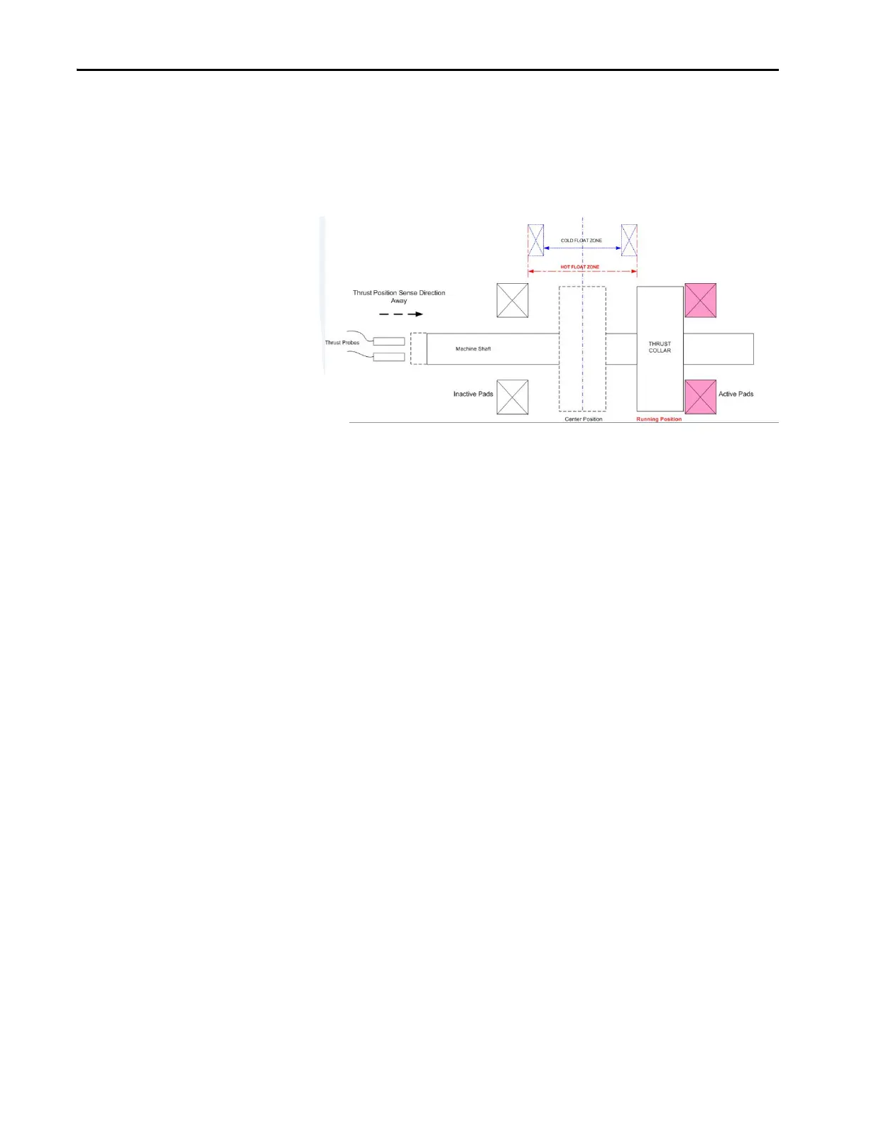
Steam turbines normally “Thrust” toward the Exhaust End of the machine. For
example, from the High-pressure end toward the Low-pressure end. The
turbines normally have the thrust bearing positioned at the HP end of the
machine as shown in the following diagram.
The thrust probes are also at this end of the machine, therefore, the direction of
normal thrust is away from the probes.
It is difficult, if not impossible, to set the rotor in the middle of the float.
Normal practice is to locate the rotor hard against the active thrust pads and
use it as the zero position.
The probe gap is then adjusted to the middle of its linear range typically setting
the gap to -10 Vdc, which is equivalent to 1.27 mm (50mils), for a probe
sensitivity of 7.87 V/mm (200mv/mill).
The offset value is entered as 10V DC in this example when using the Volts
selection, or 1.27 mm (50 mils) when using the EU selection. This assumes a
probe sensitivity of 7.87 V/mm (200 mv/mil). The sense control is set to Away.
This setup also means that movement toward the active pads results in
increasingly negative gap voltage.
 Loading...