180 Rockwell Automation Publication 1444-UM001D-EN-P - June 2018
Chapter 4 Measurement Definition
Channel 1/3 DC Page Configuration
The 1444 monitor requires that the long side sensor is input to the second
channel of the pair.
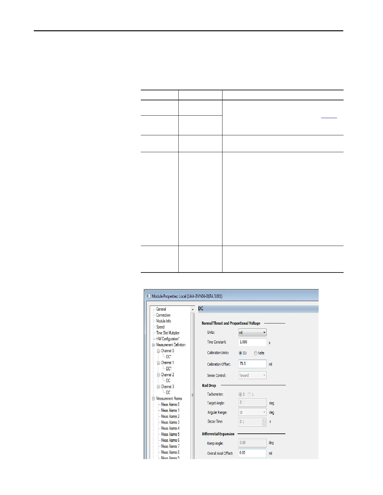
Figure 74 - Module Properties - Long Side Sensor
Table 38 - Axial Differential Expansion Configuration - Long Side Sensor
Parameters Values Comments
Units Select from presented
displacement units
Differential Expansion measurements are made using eddy current
probes. Configuration of the units, time constant, and calibration
units are the same as for Normal Thrust measurements (page 156
).
Sense control is fixed at “Toward” for the long side probe.
Time constant 0.1…60.0 seconds
Calibration Units EU (0)
Volts (1)
Select EU
Calibration offset -50000…50000 For the long side probe, the offset is a combination of the entire
measured range of channel 0/2, as well as the entire offset of
channel 1/3. The latter is due to the measurement starting at the
lowest voltage, so the range from 0 to -17.7 (in the example) must
be accounted for.
Using the above 8 mm probe example:
9.8...88.6 mils (0.25...2.25 mm) gives a measurement range of 78.8
mils (2.0 mm) from the short side sensor channel (channel 0/2).
Add to that the measured distance from total range of the long side
sensor, 88.6 mils (2.25 mm) to get a combined total of 167.4 mils
(4.25 mm).
With the Calibration Units set to EU, the offset can be entered
directly.
Overall axial offset -50000…50000 No value must be entered into the Overall Axial Offset entry box
unless the starting value for the expansion measurement is required
to start at other than a zero value due to DCS or other control system
requirements.

 Loading...