224 Rockwell Automation Publication 1444-UM001D-EN-P - June 2018
Chapter 8 Configure Alarms
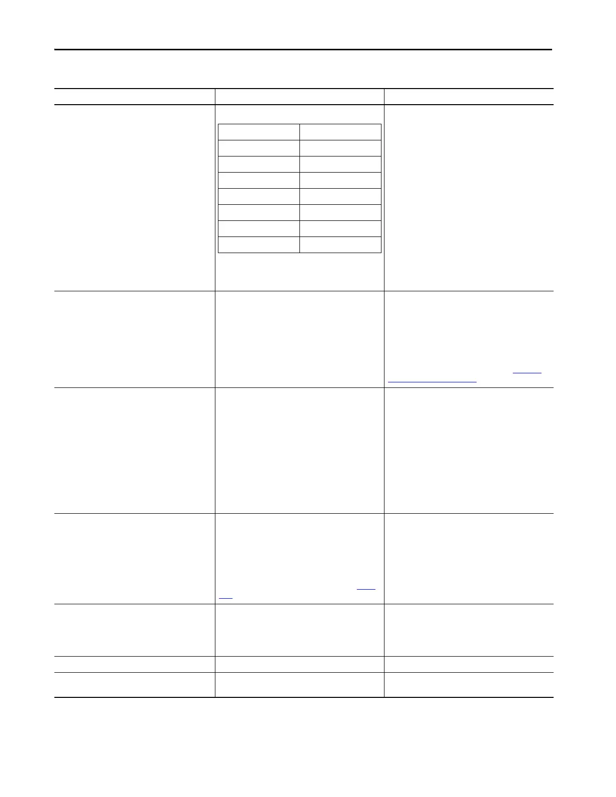
Logic Select from:
The Logic control uses the form “A out of B”. In all cases, the
number “B” refers to the first B entries in the
Measurement Alarm Input list.
For the Voted Alarm to evaluate to TRUE, the requisite
number of its inputs* must have a status of any of the
types that are enabled per Alarm Status to Activate On.
*Per this Logic definition
IMPORTANT: The selected logic must reference only
enabled Measurement Alarms. For example, if the selected
logic is “1 Out of 3” then the Measurement Alarms
referenced by inputs 0, 1 and 2 must be enabled.
Setpoint Multiplier Trigger – Control 0/1 Select Control 0 or 1 Select Control 0 to use Controller Output Control Tag SPM 0
to manage the Setpoint Multiplier function.
Select Control 1 to use Controller Output Control Tag to
manage the Setpoint Multiplier function.
To use Logic (Discrete) Inputs, the specific input must also
be defined to apply to the SPM function (See Hardware
Configuration Page on page 111).
Setpoint Multiplier Trigger –Hold 0.000…65.500 seconds The time that the alarm (threshold) multiplier is applied
after the control is toggled.
The SPM control, either a physical switch or the specified
bit on controller output, starts (or restarts) the TIMER each
time the control toggles.
A toggle occurs when the state changes, such as when the
control changes from OFF/UNSET to ON/SET, or ON/SET to
OFF/UNSET.
IMPORTANT: When SPM is used, the hold time must be
set to ≥1 second.
Gating Speed – Reference Select from:
•Off
•Speed 0
•Speed 1
• Factored Speed 0
• Factored Speed 1
Speed 0/1 is presented only if defined and Factored Speed
0/1 is presented only if the factor value is >0 (see Speed
Page).
Select the speed source to use as the reference in speed
gating of this Voted Alarm.
Gating Speed – Condition Select from:
• Greater Than High Speed
• Less than Low Speed
• Inside Window
•Outside Window
Select the condition to apply in the speed gating logic.
Gating Speed – High Limit >0 The high-speed threshold.
Gating Speed – Low Limit >0 The low speed threshold. Must be less than the High-
Speed limit.
Table 47 - Voted Alarms (continued)
Parameter Name Values Comments
1 Out Of 1 1 Out Of 4
1 Out Of 2 2 Out Of 4
2 Out Of 2 3 Out Of 4
1 Out Of 3 4 Out Of 4
2 Out Of 3 1 Out Of 2 AND 1 Out Of 2
3 Out Of 3 2 Out Of 2 OR 2 Out Of 2
1 Out Of 2 AND 2 Out Of 2
2 Out Of 2 AND 1 Out Of 2
 Loading...