Rockwell Automation Publication 1444-UM001D-EN-P - June 2018 315
Operate the Module Chapter 10
Startup Behavior
At startup, the group of four is used to indicate the configured bus address of
the expansion module.
Identification of the module address is provided by turning on one or more of
the relay light-emitting diodes.
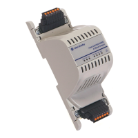
Figure 96 - Relay LEDs
The specific light-emitting diodes that are illuminated indicate the modules
address:
1. Module address 1 – light-emitting diode R3 blinks blue
2. Module address 2 – light-emitting diode R2/R3 blinks blue
3. Module address 3 – light-emitting diode R1/R2/R3 blinks blue
The indication continues for approximately four seconds.
During this period, all controllable status indicators, except indicators that
display the address, are unlit (the green status indicator to the left is the
hardware-controlled, power status indicator).

 Loading...