42 Rockwell Automation Publication 1444-UM001D-EN-P - June 2018
Chapter 2 Install the Dynamix 1444 Series Monitoring System
When you install the system, follow these instructions and install/configure
the components in this order.
1. Review the safety instructions.
2. Review the network connectivity considerations.
3. Review the system design guidelines, considerations, and requirements.
4. Mount the terminal base.
5. Establish expansion bus connections between modules.
6. Configure the main terminal base.
7. Configure the Auxiliary relay terminal base.
8. Configure the Auxiliary 4
…20 mA terminal base.
9. Configure the Auxiliary TSC terminal base.
10. Install the module.
11. Configure the main module connectors.
12. Configure the main module transducers.
13. Configure the expansion module connectors.
14. Start the module and perform a self-test.
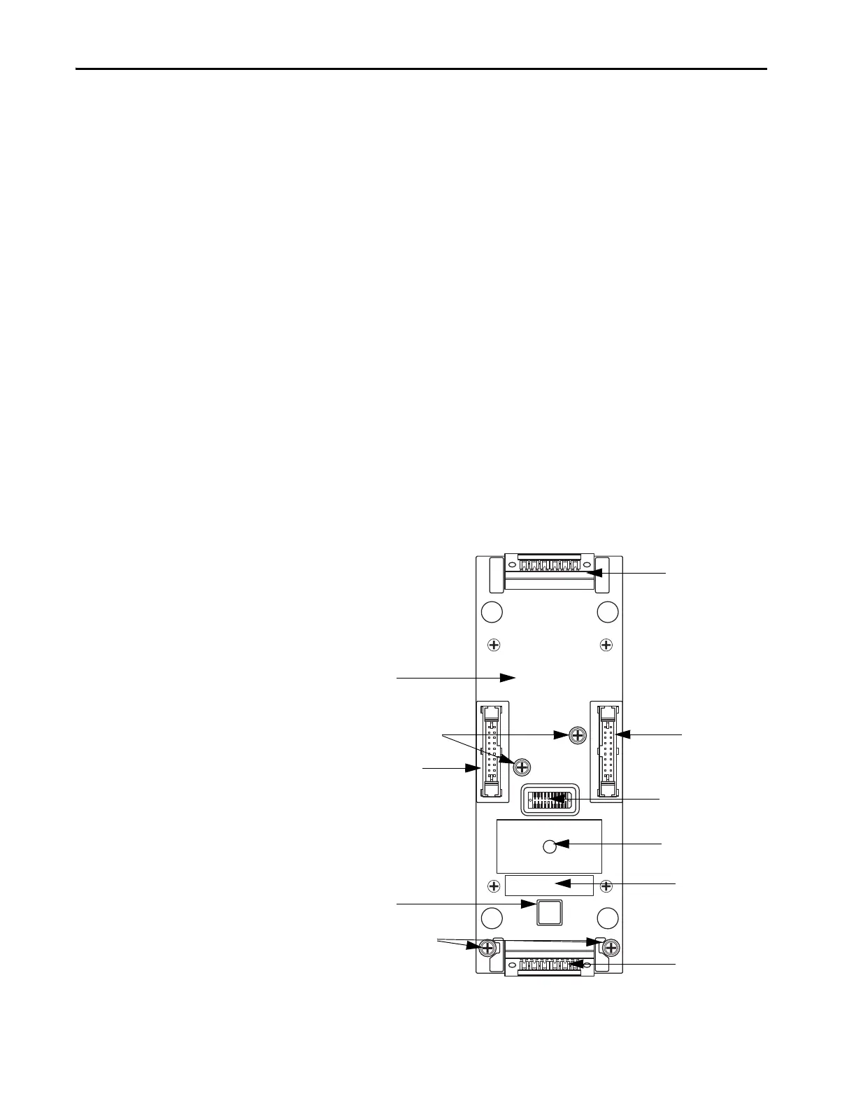
Figure 5 - Expansion Terminal Base – Overview
PID label area
Upper base connector
Left EXP bus connector
Address switches
Lower base connector
Module type label area
PID label area
Base-to-module
connector
Right EXP bus
DIN rail set screws (two ea)
Bottom set screws (two ea)
 Loading...