Rockwell Automation Publication 1444-UM001D-EN-P - June 2018 487
CIP Objects Appendix A
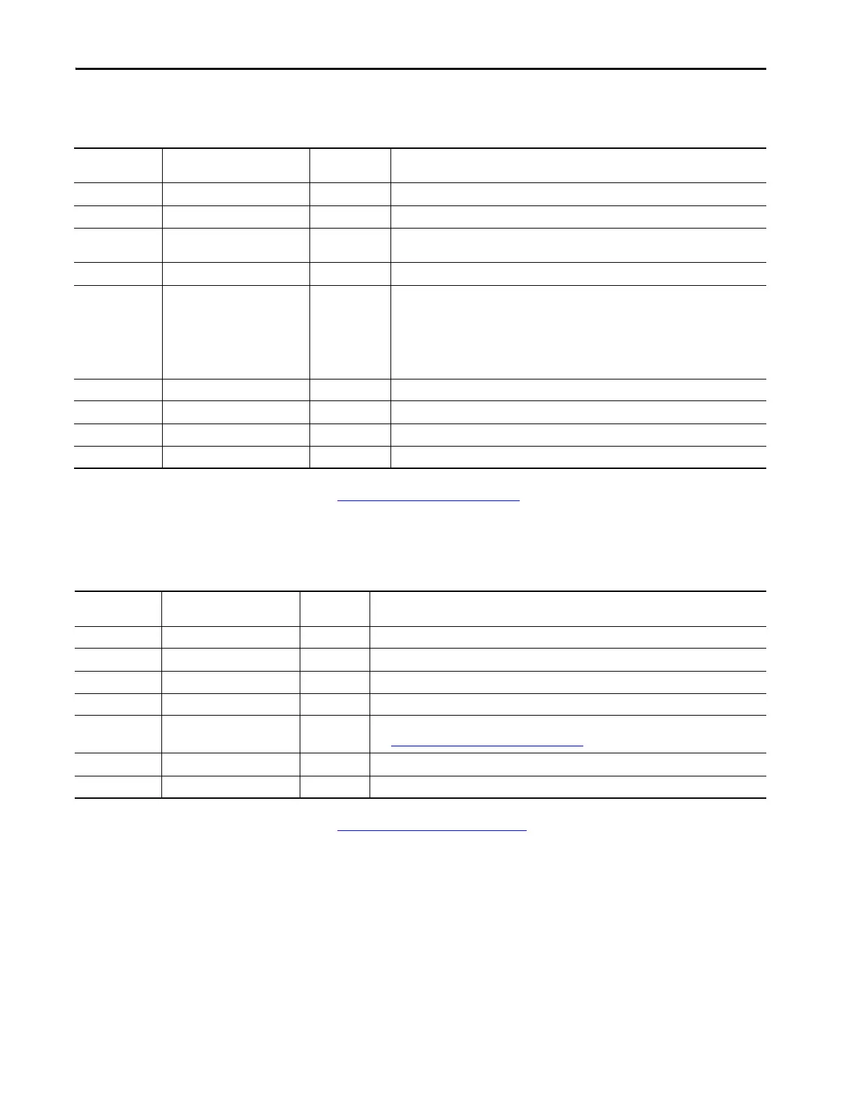
The Record Type Structures are as follows.
See Reading FFT Data
on page 333 for details on how to calculate the FFT
from the read data.
Reference the measurement tables.
See Reading TWF Data
on page 332 for details on how to calculate the TWF
from the read data.
Table 233 - FFT (eFFT)
Byte Offset
Within Structure
Structure Member Data Type Description
0 TimestampNanoSec UDINT Subsecond accuracy.
4 TimestampSec UDINT Seconds since 1970.
8 SamplePeriodInSecs REAL Time period between samples or speed and number of samples per revolution can be used to
calculate the bandwidth for the FFT.
12 Identifier DWORD Data source, mode, tacho source, and measurement units.
16 ucDataSelect BYTE If Bit 0 is set, phase array follows the mag array in the returned data array. Otherwise, just the
magnitude array is returned.
Bits 1 and 2 indicate FFT scaling: 0 Peak, 1 Peak to Peak, 2 RMS.
Bits 3 and 4 indicate the data filtering that has been applied.
Bits 5 and 6 indicate the FFT Windowing applied: 0 Normal/Rectangular, 1 Flat-Top, 2 Hanning,
3 Hamming.
17 Reserved1 BYTE
18 Reserved2 UINT
20 ByteCount UDINT The size of the following array in bytes.
24 LineArray REAL The array of FFT line amplitude data.
Table 234 - Waveform (eTWF2)
Byte Offset
Within Structure
Structure Member Data Type Description
0 TimestampNanoSec UDINT Subsecond accuracy.
4 TimestampSec UDINT Seconds since 1970.
8 SamplePeriodInSecs REAL Time period between samples or speed and number of samples per revolution.
12 Identifier DWORD Data source, mode, tacho source, and measurement units.
16 RelativeTime UDINT A 24-bit (micro-second) counter-value for finely aligning data.
See Reading Continuous Time Waveforms
on page 329 for information on using this parameter.
20 ByteCount UDINT The size of the following array in bytes.
24 SampleArray REAL The array of waveform data values (samples).
 Loading...