Rockwell Automation Publication 1734-UM001E-EN-P - July 2013
Troubleshoot with the Indicators 141
Troubleshoot Digital
Modules
The I/O status indicators provide input and output indications for each module.
Individual meanings are indicated in the tables.
1734-IB2, 1734-IB4, and 1734-IB8 Sink Input Modules
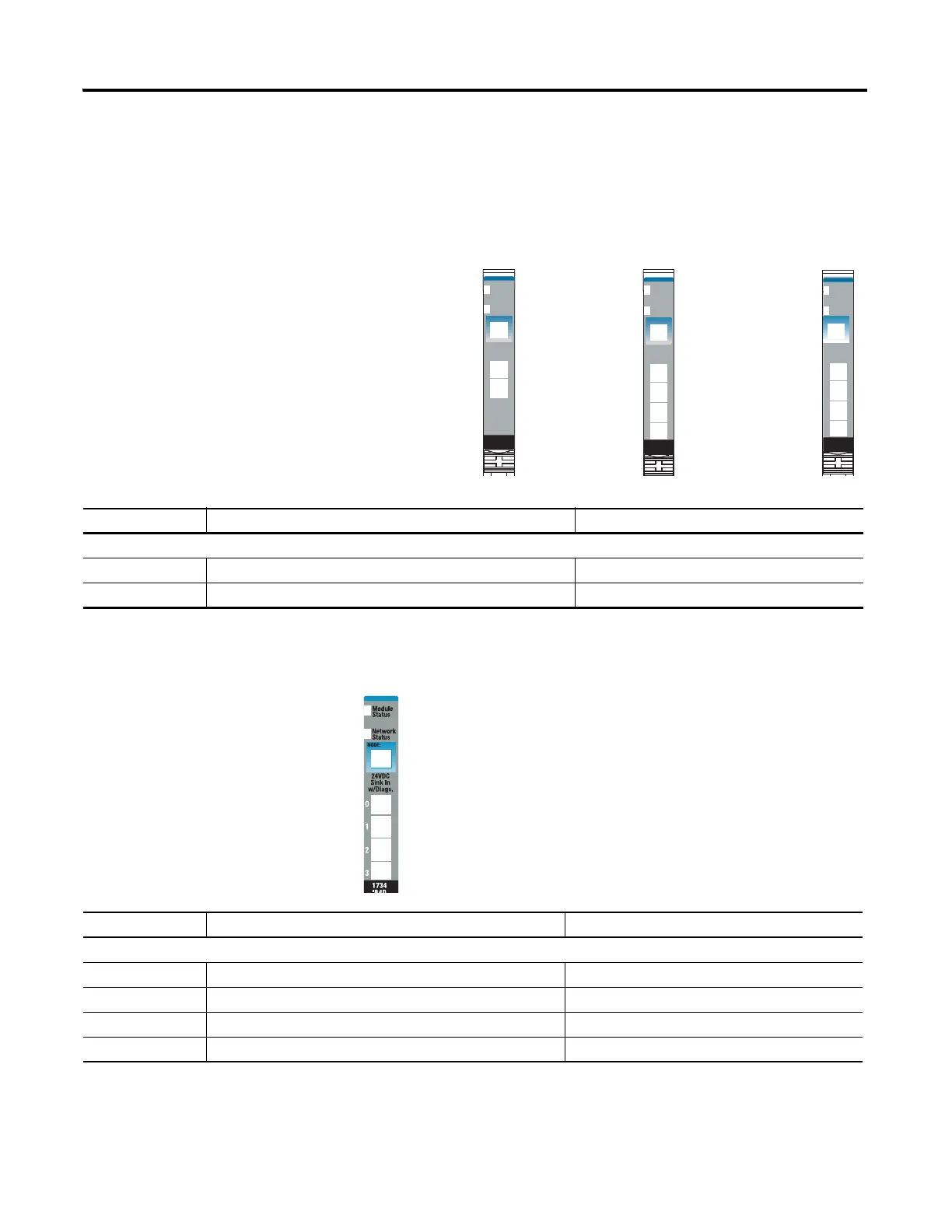
1734-IB4D Sink Input Modules with Diagnostics
Module Status
Network Status
Status of Input 0
Status of Input 1
24VDC
Sink
Input
Module
Status
Network
Status
1734
IB4
NODE:
0
1
2
3
24VDC
Sink
Input
Module
Status
Network
Status
1734
IB2
NODE:
0
1
1734-IB2
1734-IB4
1734-IB8
Status of Input 0 & 4
Status of Input 1 & 5
Status of Input 2 & 6
Status of Input 3 & 7
Module Status
Network Status
24VDC
Sink
Input
Module
Status
Network
Status
1734
IB8
NODE:
0
1
2
3
4
5
6
7
Status of Input 2
Status of Input 3
Status of Input 0
Status of Input 1
Indication Probable Cause Recommended Action
I/O Status
Off Input is in the off-state. None.
Yellow Input is in the on-state. None.
Module Status
Network Status
Status of Input 0
Status of Input 1
Status of Input 2
Status of Input 3
46136
Indication Probable Cause Recommended Action
I/O Status
Off Input is in the off-state. None.
Yellow Input is in the on-state. None.
Red Short circuit detected. Check I/O wiring or terminal base.
Flashing red Open wire detected. Check I/O wiring or terminal base.
 Loading...


