Rockwell Automation Publication 1734-UM001E-EN-P - July 2013
14 Install POINT I/O Modules
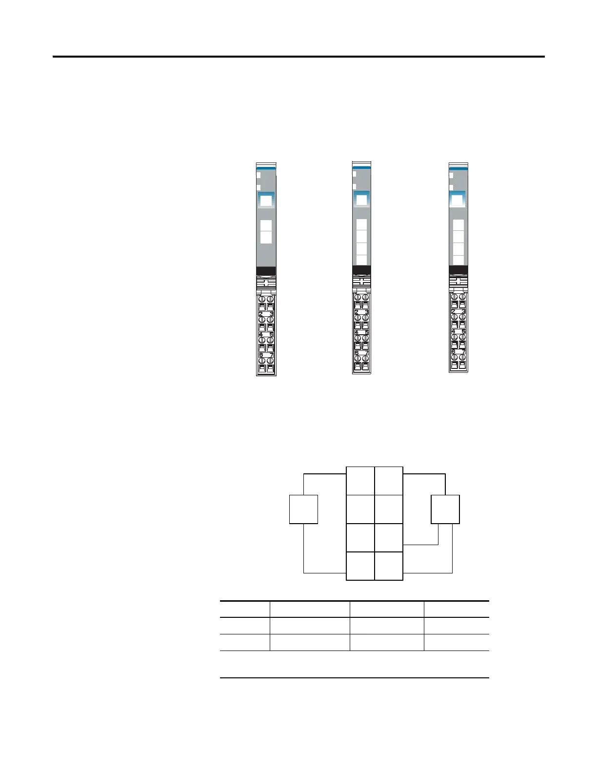
Wiring Digital Modules
Refer to this section to wire digital modules.
1734-IB2, 1734-IB4, and 1734-IB8 Sink Input Modules
1734-IB2 Module Wiring Diagram
24VDC
Sink
Input
Module
Status
Network
Status
1734
IB2
NODE:
0
1
24VDC
Sink
Input
Module
Status
Network
Status
1734
IB4
NODE:
0
1
2
3
24VDC
Sink
Input
Module
Status
Network
Status
1734
IB8
NODE:
0
1
2
3
4
5
6
7
Status of Input 0
Status of Input 1
Input 0
NC
C
V
Input 1
NC
C
V
Input = 0 and 1
NC = No Connection (2 and 3)
C = Common (4 and 5)
V = Supply (6 and 7)
Input 0
C
V
Input 1
C
V
Input 2 Input 3
Status of Input 2
Status of Input 3
Input = 0, 1, 2 and 3
C = Common (4 and 5)
V = Supply (6 and 7)
1734-IB2
1734-IB4 1734-IB8
Input 0
Input 1
Input 2 Input 3
Input 4
Input 5
Input 6 Input 7
Input = 0, 1, 2, 3, 4, 5, 6 and 7
V and C are daisychained from either the adapter,
1734-FPD module, 1734-EP24DC power supply, or a
user-supplied auxiliary terminal block.
Status of Input 0
Status of Input 1
Status - Input 0 & 4
Status - Input 1 & 5
Status - Input 2 & 6
Status - Input 3 & 7
Channel Input Common Voltage
00 4 6
11 5 7
Connect common on 3-wire proximity switches. 12/24V DC is supplied
through the internal power bus.
Prox
In 0 In 1
NC
C
VV
C
NC
Prox
V = 12/24V DC
C = Common
3-wire
Sink Input
2-wire
3
5
7
01
2
4
6
 Loading...


