Rockwell Automation Publication 1734-UM001E-EN-P - July 2013
148 Troubleshoot with the Indicators
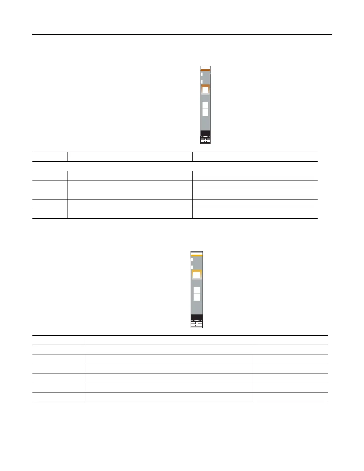
1734-IE2V Analog Voltage Input Module
1734-OE2V Analog Voltage Output Module
41974
Module Status
Network Status
Status of Input 0
Status of Input 1
Analog
Voltage
Input
Module
Status
Network
Status
1734
IE2V
NODE:
0
1
Indication Probable Cause Recommended Action
Channel Status
Off Module is in CAL mode. None.
Solid green Normal operation present with channel scanning inputs. None.
Flashing green Channel being calibrated. None.
Solid red No power or major channel fault present. Apply field power, or replace module, as needed.
Flashing red Channel is at end of range (-0.25, -10.25, or +10.25V). Operate within normal range.
41974
Module Status
Network Status
Status of Output 0
Status of Output 1
Analog
Voltage
Output
Module
Status
Network
Status
1734
OE2V
NODE:
0
1
Indication Probable Cause Recommended Action
Channel Status
Off Module is in CAL mode. None.
Solid green Normal operation present with channel actively controlling outputs. None.
Flashing green Channel being calibrated. None.
Flashing red A Low or High Clamp alarm is present. Operate within normal range.
Solid red No field power is present. Apply field power.
 Loading...


