Rockwell Automation Publication 1734-UM001E-EN-P - July 2013
Chapter
4
POINT I/O Module Data
About This Chapter
Read this chapter for information about module status, input, output, and
configuration data, and default data maps forPOINT I/O modules to include
the following:
• Digital Input Modules
• Digital Output Modules
• Relay Output Modules
• Analog Input Modules
• Analog Output Modules
• POINTBlock I/O Modules
Digital Input Modules
Read this section for information about digital input modules.
Digital DC Input Modules
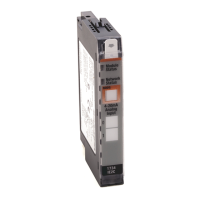
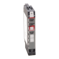
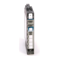
The 1734 digital DC input modules feature the following:
• 24V DC nominal DC inputs
• Input range of 10...28.8V dc
• 2, 4, or 8 sinking or sourcing style inputs
• Autobaud (will match baud of existing devices on the network)
• Selectable input filter times (0…65 ms with 1 ms default)
• Sequential auto addressing
I/O messages are sent to (consumed) and received from (produced) these
POINT I/O modules. These messages are mapped into the processor memory.
(1)
These POINT I/O modules produce one byte of input data (scanner Rx). They
do not consume I/O data (scanner Tx).
(1) These are mapped through scan lists in DeviceNet networks and Direct, Listen Only, or Rack Optimized
connections in ControlNet and EtherNet/IP networks.

 Loading...
