Rockwell Automation Publication 1734-UM001E-EN-P - July 2013
Install POINT I/O Modules 51
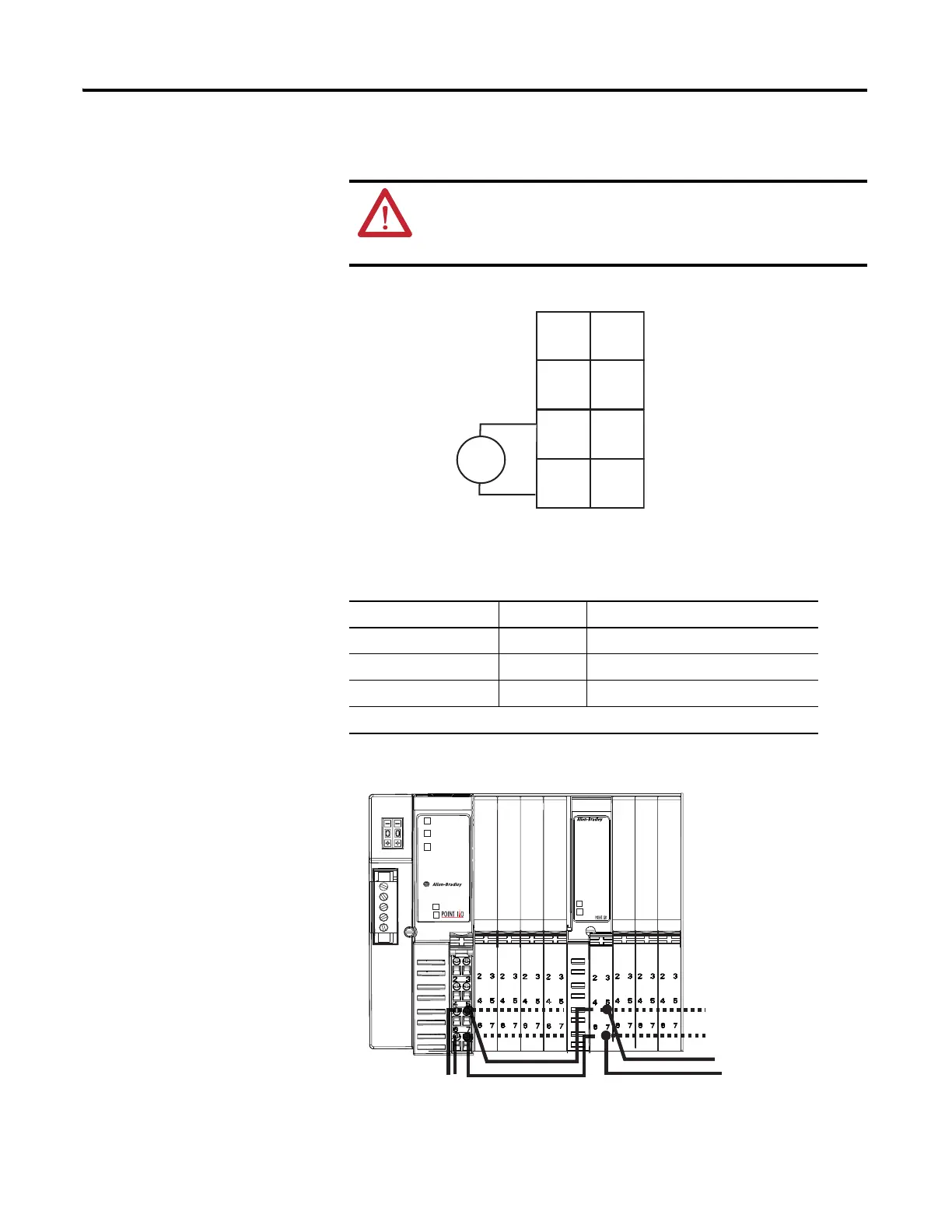
12/24V DC Wiring Diagram
Example of Continuing Power
ATTENTION: Use the 1734-EP24DC expansion power supply only with
adapter class products. This 1734-EP24DC power supply cannot be used
with a 1734-PDN module or 1734D POINTBlock modules. Do not connect
120/240V AC power to this supply.
Connect Terminal Terminals (for continuing power)
+V DC 6 7
-V DC 4 5
Chas Gnd 2 3
12/24V DC becomes the internal power bus for modules to the right.
NC NC
C
VV
C
V DC
V = 12/24V DC, C = Common
CHAS GND = Chassis ground
This DC supply is
connected to the
internal power bus.
3
5
7
01
2
4
6
Do not connect 120/240V AC
power to this supply.
CHAS
GND
CHAS
GND
0101 01 01 0101 0101
Adapter
Status
DeviceNet
Status
PointBus
Status
1734-ADN
DeviceNet
Power
System
Power
1734-EP24DC
DeviceNet
Power
System
Power
EP24DC
ADN
Example of continued power.
12/24V DC only
1734adn4
O
B
2
E
O
B
4
E
I
B
4
I
B
2
I
E
2
C
I
E
2
V
O
E
2
C
 Loading...


