Rockwell Automation Publication 1734-UM001E-EN-P - July 2013
Install POINT I/O Modules 21
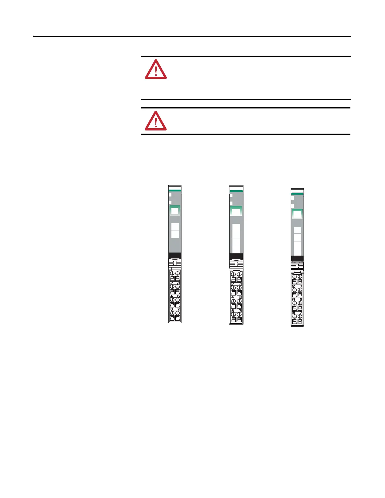
1734-OB2E, 1734-OB4E, 1734-OB8E, 1734-OB2, 1734-OB4, and
1734-OB8 Protected Output Modules
WARNING: When you connect or disconnect wiring while field side
power is on, an electrical arc can occur. This could cause an explosion in
hazardous location installations.
Be sure that power is removed or the area is nonhazardous before
proceeding.
ATTENTION: When connecting more than one wire in a termination
point, make sure that both wires are the same gauge and type.
24VDC
Source
Output
Module
Status
Network
Status
1734
OB4E
0
1
2
3
NODE:
24VDC
Source
Output
Module
Status
Network
Status
1734
OB8E
0
1
2
3
NODE:
4
5
6
7
42016
Module Status
Network Status
Status of Output 0
Status of Output 1
Status of Output 3
Output 0
Output 0
C
C
Output 1
Output 1
C
C
24VDC
Source
Output
Module
Status
Network
Status
1734
OB2E
NODE:
0
1
Output 0
Output 2
Output 1
Output 3
C
C
V
V
C = Common
V = Supply
1734-OB2E
1734-OB4E
Output 0
Output 2
Output 1
Output 3
Output 4
Output 6
Output 5
Output 7
1734-OB8E
Status of Output 0 & 4
Status of Output 1 & 5
Status of Output 2 & 6
Status of Output 3 & 7
Status of Output 2
Status of Output 0
Status of Output 1
 Loading...


