Rockwell Automation Publication 1734-UM001E-EN-P - July 2013
Install POINT I/O Modules 33
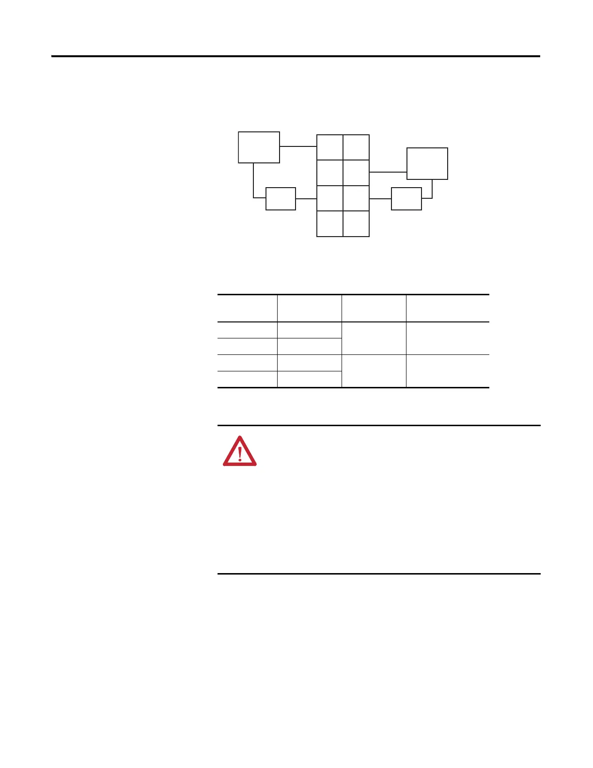
1734-OX2 Modules with Load Powered by External Power Bus
Wiring Diagram
Channel Output Relay
Common
Supply
(1)
(1) Supply voltage can range from +5V DC…240V AC, depending on relay load. 12V, 24V DC,
120V, 240V AC power for the module is provided by the internal power bus
0 (N.C.) 0 4 6
0 (N.O.) 2
1 (N.C.) 1 5 7
1 (N.O.) 3
ATTENTION: Do not attempt to increase load current or wattage
capability beyond the maximum rating by connecting two or more
outputs in parallel. The slightest variation in relay switching time may
cause one relay to momentarily switch the total load current.
Make certain that all relay wiring is properly connected before applying any
power to the module.
Total current draw through the wiring base unit is limited to 10 A. Separate
power connections to the terminal base unit may be necessary.
Use the end cap from your adapter or interface module to cover the exposed
interconnections on the last mounting base on the DIN rail. Failure to do so
could result in equipment damage or injury from electric shock.
+V
+V
Out 0
NC
Out 1
NC
Out 1
NO
Load
Power
Out = Output channel relay contacts
Power Supply = can range from +5V DC…240V AC
RC = Relay Common
0
2
4
6
3
5
7
1
Power
Supply
Load
L1
L2/N
L1
L2/N
Out 1
RC
Out 0
RC
Out 0
NO
 Loading...


