Rockwell Automation Publication 1734-UM001E-EN-P - July 2013
46 Install POINT I/O Modules
Wiring Power Distribution
and Other Modules
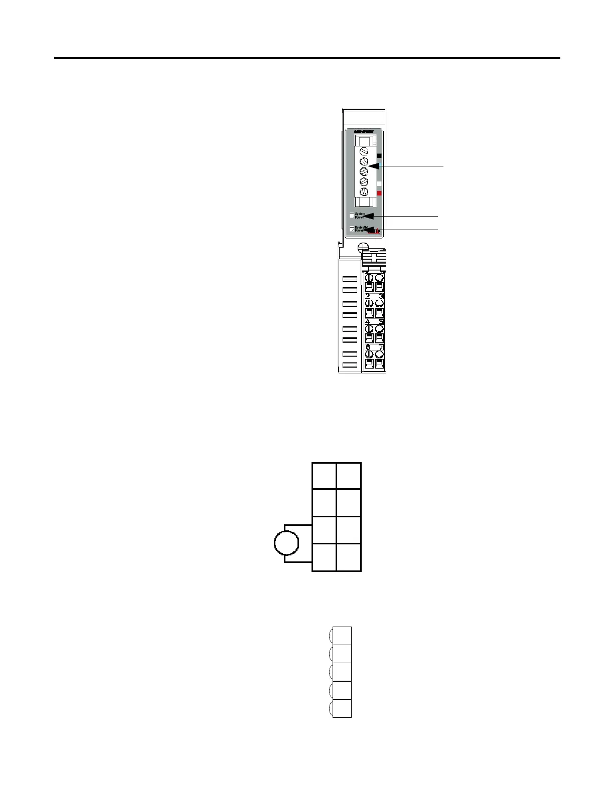
1734-PDN Communication Interface Module
1734-PDN Module Wiring Diagram
41970
System Power
CHAS GND
C
V
NC
CHAS GND
C
V
NC
DeviceNet Connector
DeviceNet Power
NC = No Connection
CHAS GND = Chassis Ground
C = Common
V = Supply
V DC
NC
CHAS
GND
C
V
NC
C
V
This supply will be
connected to the internal
field power bus.
12/24V DC
Power
NC = No Connection
CHAS GND = Chassis Ground
C = CommonV = Supply
CHAS
GND
3
5
7
0
1
2
4
6
DeviceNet
connection
Black
Blue
Bare
White
Red
-V
CAN - Low
Shield
CAN - High
+V
1
2
3
4
5
 Loading...


